The USB-C specification rates connectors for 10,000 insertion cycles — a number that satisfies the marketing and misleads the field. Real USB-C connectors fail earlier, and the failures cluster around a specific mechanism: the retention features that hold the plug in the receptacle wear, the mating force drifts, and the connection that once clicked firmly begins to feel loose. For industrial and OEM applications, where a loose connection is a data-drop or a power-loss event, understanding the wear mechanism is the difference between a durable assembly and a warranty line. This guide covers the mechanics, the failure modes and the specification answers.
The Mechanics: What Holds a USB-C Plug In
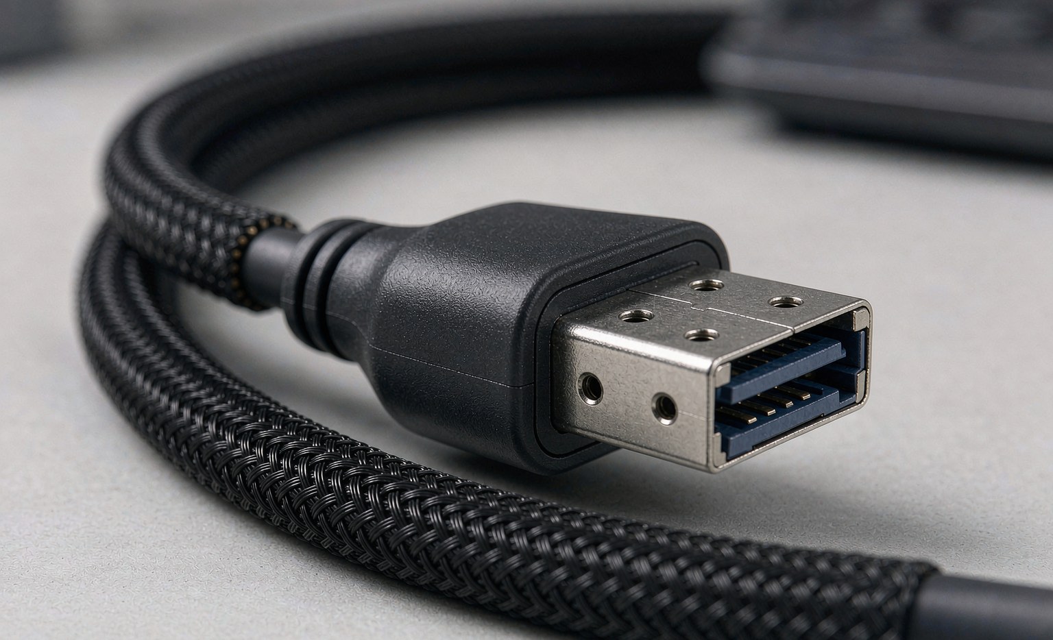
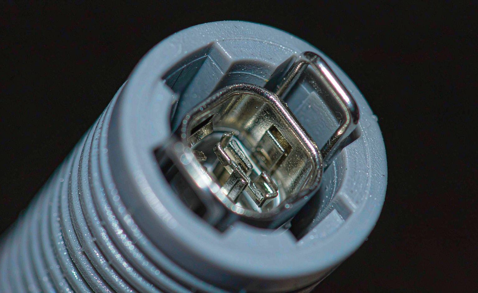
A USB-C connection is held by the receptacle’s retention features engaging the plug’s shell — the spring contacts inside the receptacle tongue grip the plug, and the symmetrical shell geometry keeps it centred. Mating force is a designed compromise: too little and the connection loosens under vibration; too much and insertion wears the contacts and the user fights the plug. Over cycles, three things wear: the receptacle’s spring contacts lose their spring force, the plug’s shell wears at the contact points, and the centring features that keep the pair aligned erode.
| Component | Function | Wear mode |
|---|---|---|
| Receptacle spring contacts | Retention and wiping action | Loss of spring force over cycles; contact resistance rises |
| Plug shell | Centring and retention engagement | Wear at engagement points; fit loosens |
| Centring features | Alignment of the 24 pins | Erosion allows misalignment, uneven contact wear |
| Cable strain relief | Keeps cable loads off the connector | Failure transmits cable motion into the connector |
The strain-relief row is the most underrated: most “connector failures” in the field are cable-side failures where motion at the strain relief transmits into the connector shell, accelerating every wear mode above. The cable and connector have to be specified as one assembly — the principles in our wire gauge and power rating guide apply to the whole chain, not just the copper.
Why Real-World Life Falls Short of the Rating
The 10,000-cycle rating is measured under laboratory conditions: clean connectors, perpendicular insertion, controlled force. Field life is shorter for reasons that are all visible in advance. Angled insertion wears the retention features unevenly. Contamination — pocket lint, dust, metal shavings — abrades the contacts and interferes with retention. Higher-power operation heats the assembly, and heat accelerates contact oxidation and relaxes spring temper. And vibration environments, the defining condition of industrial duty, multiply each cycle’s wear.
| Field factor | Effect on life | Specification response |
|---|---|---|
| Angled insertion | Uneven retention wear, pin damage | Receptacle placement; cable length that encourages straight entry |
| Contamination | Contact abrasion, retention interference | Sealed or recessed receptacles; cleaning protocol |
| Heat from power delivery | Oxidation, spring relaxation | Current derating; thermal-aware assembly design |
| Vibration | Fretting, retention loss | Locking mechanisms; strain relief; secured runs |
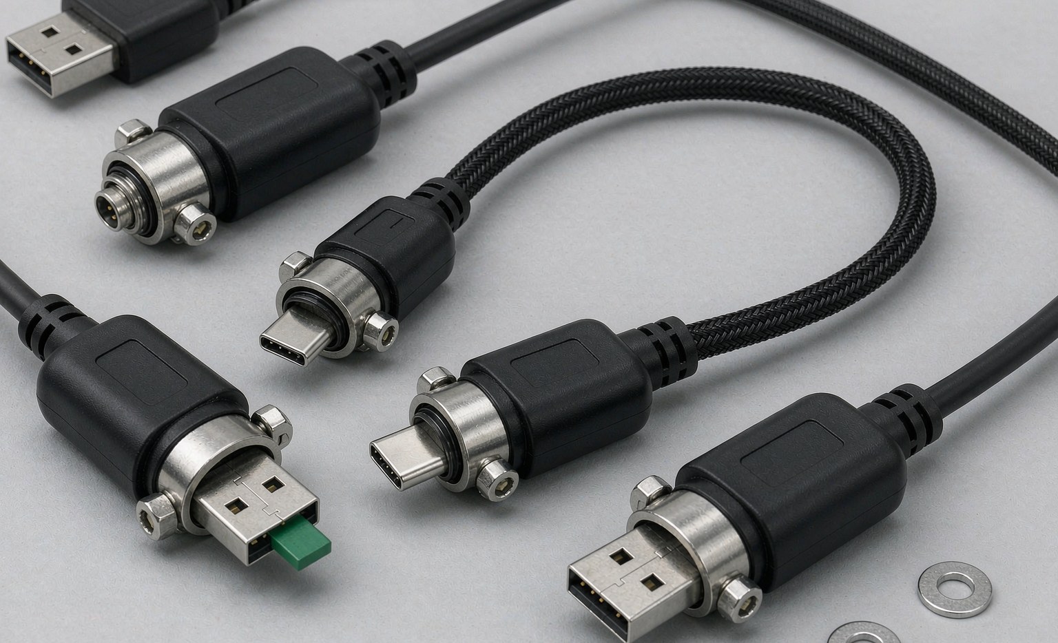
Vibration deserves emphasis because it is where industrial USB-C diverges from consumer USB-C. In a moving machine, an unlocked USB-C connection will frett — micro-motion between contacts that wears plating and raises resistance until the connection fails intermittently. The engineering answer is the locking family covered in our screw-locking USB-C guide and the field rationale in our field engineer’s USB-C design guide: where vibration exists, locking is not an accessory but the durability feature.
Specifying a Durable Assembly
For OEM and industrial buyers, the specification should treat durability as a set of measurable properties rather than a marketing adjective. The items worth specifying explicitly: receptacle and plug connector ratings (cycle life at the rated current, not the nominal), plating thickness and material on the contacts (gold plating thickness directly trades cost against wear life), the retention force spec and its tolerance, the strain-relief design and its bend-radius rating, and — where the environment demands it — the locking mechanism and its vibration profile.
The power context matters to durability as well: an assembly carrying high current runs hotter, and heat is the accelerant for every wear mode. The relationship between current, wire gauge and thermal behaviour is covered in our wire gauge and power rating guide, and the high-power certification requirements in our e-marker and 240 W guide. An assembly specified for 240 W that runs at its limit is a hotter assembly, and its connector life is shorter than the same connector at 60 W — a trade the specification should acknowledge rather than discover in the field.
Frequently Asked Questions
Is 10,000 cycles a realistic expectation?Under lab conditions, yes. In the field with angled insertion, contamination and heat, plan on fewer — and in vibration environments, specify locking regardless of cycle rating.
What causes a USB-C connection to feel loose?Almost always retention-feature wear — the receptacle’s spring contacts or the plug’s shell engagement points. Once looseness is perceptible, the contact resistance and signal integrity have already degraded.
Does gold plating thickness really matter?Yes — plating thickness is one of the clearest cost-versus-durability trades in connector selection, and it is one of the first places value engineering cuts the wrong corner.
Technical background: {{OUT:https://en.wikipedia.org/wiki/USB-C|USB-C connector design}}, {{OUT:https://en.wikipedia.org/wiki/Gold_plating|contact plating and wear}} and {{OUT:https://en.wikipedia.org/wiki/Fretting|fretting corrosion}} cover the engineering concepts referenced above.