An industrial USB cable looks identical to a consumer cable until it fails. In a machine-vision cell, a PLC cabinet or a drag-chain on a robot arm, the failure modes are mechanical and electrical at the same time: the connector backs out under vibration, the braid opens at the strain relief, or the differential pair drifts out of impedance and the camera starts dropping frames. This guide explains how industrial USB cables are specified and built — retention classes, speed-versus-length limits, internal construction and the electrical tests that separate a compliant assembly from a catalogue part.
Consumer vs industrial USB cable: what actually changes
Consumer USB cable is optimised for cost in a stationary, air-conditioned environment. Industrial USB cable is optimised for retention, shielding and flex life. Four differences matter:
| Property | Consumer cable | Industrial cable |
|---|---|---|
| Retention | Friction latch, ~8–20 N | Screw-lock or latching, 50–100 N |
| Shielding | Foil only on some builds | Foil + braid, drain wire bonded to shell |
| Jacket | PVC | PUR / TPE, drag-chain rated |
| Strain relief | Two-piece moulding | Over-moulded single-piece boot |
Generic consumer cables are also frequently under-built: third-party testing routinely finds copper-clad aluminium in place of pure copper, weak strain relief and insulation that cracks in service — all of which raise conductor resistance and create intermittent faults (V-Trust inspection data).
Retention classes: friction latch, screw-lock and IP67
Retention is the specification most often ignored and the one that stops a line fastest. For an industrial USB cable, retention is measured as the axial force required to disconnect the plug, and the retention class should be chosen from the environment, not from the connector footprint (TeleWire retention classification):
| Class | Mechanism | Retention force | Ingress | Typical use |
|---|---|---|---|---|
| Consumer | Internal friction latch | ~8–20 N | IP20 | Office, lab bench |
| Industrial latching | External metal tab | ~25–30 N | IP20 | Static server rack |
| Single screw-lock | 1 × M2 screw | ~50 N | IP20 | Light automation |
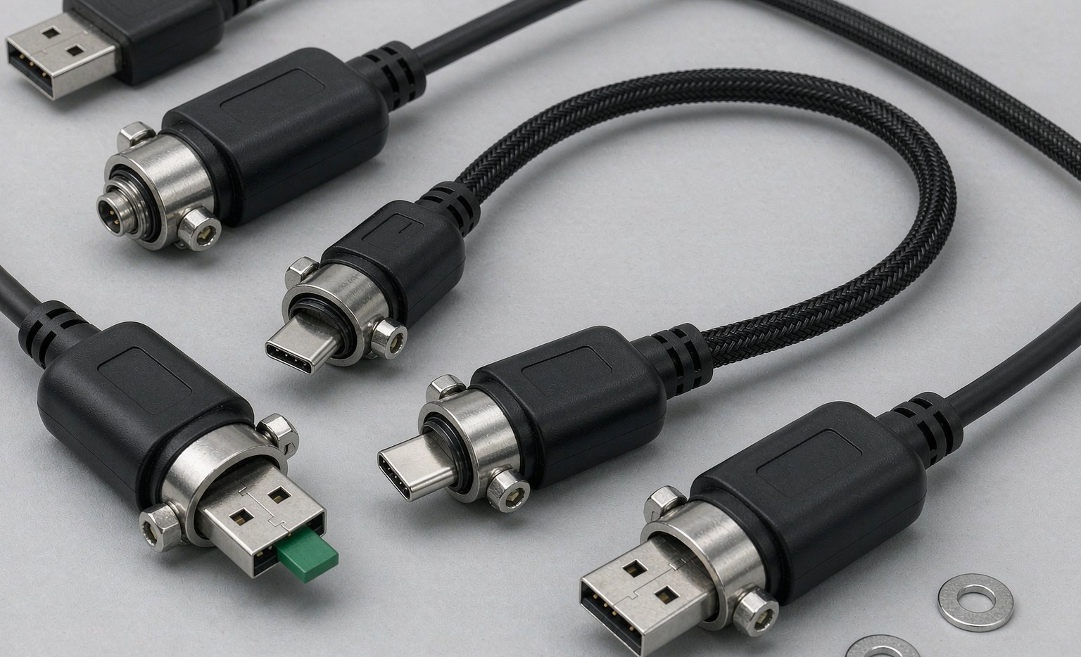
| Dual screw-lock | 2 × M2 screws | ~80 N | IP20 | Machine vision, robotics |
| Threaded coupling | Circular ring | ~100 N | IP67/68 | CNC, washdown, outdoor |
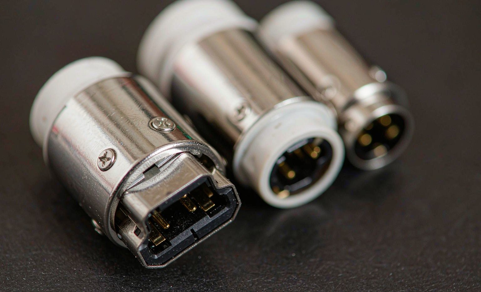
One practical note: a dual screw-lock cable only delivers its retention if the host port has matching threaded standoffs. Without them the screws spin freely and the cable behaves like a standard plug — the connector still works electrically, but the locking benefit is lost. Screw-locking USB-C and USB 3.0 assemblies are standard catalogue items in our USB cable locking range, for example the USB 3.1 Type-C with screws and the USB 3.0 A-to-B with screws.
Speed versus passive length: the limit is physics
Higher signalling rates attenuate faster in copper, so the maximum passive length falls as the data rate rises. Exceeding these limits causes signal loss, link retraining and dropped frames, not merely slower transfers — the limits are engineering constraints rather than recommendations (Newnex):
| Standard | Data rate | Max passive length | Typical application |
|---|---|---|---|
| USB 1.1 | 12 Mbps | ≤ 3 m | Legacy HID, control |
| USB 2.0 High-Speed | 480 Mbps | ≤ 5 m | 1080p cameras, PLC programming |
| USB 3.2 Gen 1 | 5 Gbps | ≤ 3 m | Machine-vision cameras |
| USB 3.2 Gen 2 | 10 Gbps | ≤ 1–3 m | 4K/8K industrial cameras |
| USB4 / Thunderbolt | 40 Gbps | ≤ 0.8–1 m | High-end vision, single-cable docks |
Beyond the passive limit the options are active extension (a repeater in the plug), an extender over Cat5e/Cat6, or an active optical cable. Active optical solutions remove EMI sensitivity over 30–100 m runs, but they cannot carry substantial USB Power Delivery, so a camera that relies on bus power needs a separate supply.
Inside the cable: construction decides signal integrity
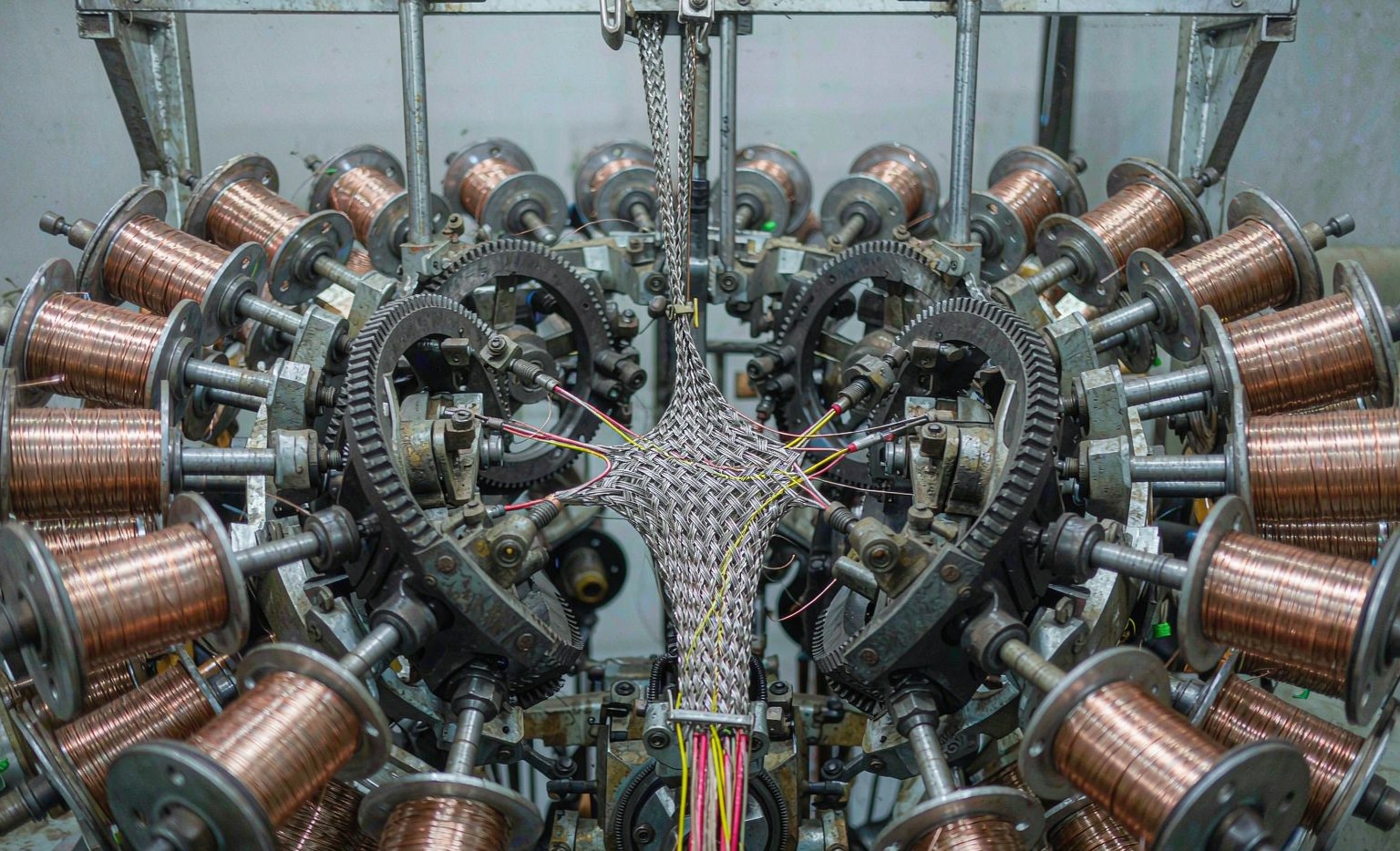
A USB 2.0 High-Speed cable is not a bundle of wires. The USB specification defines the construction in detail: a non-twisted power pair of 28–20 AWG, one 28 AWG twisted data pair with an aluminium-metallised polyester inner shield, a 28 AWG stranded tinned-copper drain wire, and an outer braid of more than 65% coverage (construction reference). The twist ratio matters as much as the gauge: the specification calls for one full twist every 60–80 mm, and deviations measurably raise common-mode interference.
| Element | Specification | Why it matters |
|---|---|---|
| Power pair | 28–20 AWG, stranded tinned copper | Sets voltage drop and IR loss at load |
| Data pair | 28 AWG, twisted 60–80 mm pitch | Differential balance, common-mode rejection |
| Inner shield | Al/PET foil, metallised face outward | Must contact the drain wire to work |
| Outer shield | Tinned-copper braid, >65% coverage | EMI immunity near VFDs and servos |
| Tensile member | Nylon / Kevlar yarn | Prevents jacket fracture under pull |
Shielding is only effective if it is grounded. The braid and foil must terminate to the connector shell or a drain wire; a shield that is not bonded to the device ground behaves as an antenna rather than a barrier.
How an industrial USB cable is manufactured
- Wire drawing and stranding — high-purity copper rod is drawn through successive dies and stranded so the conductor stays flexible.
- Insulation extrusion — the conductor is coated with PE/HDPE. Extrusion temperature and line speed set insulation concentricity, which in turn sets impedance stability.
- Pair twisting — differential conductors are twisted at a constant pitch on a precision machine.
- Cabling and shielding — cores, drain wires and fillers are laid up, then foil-wrapped and braided.
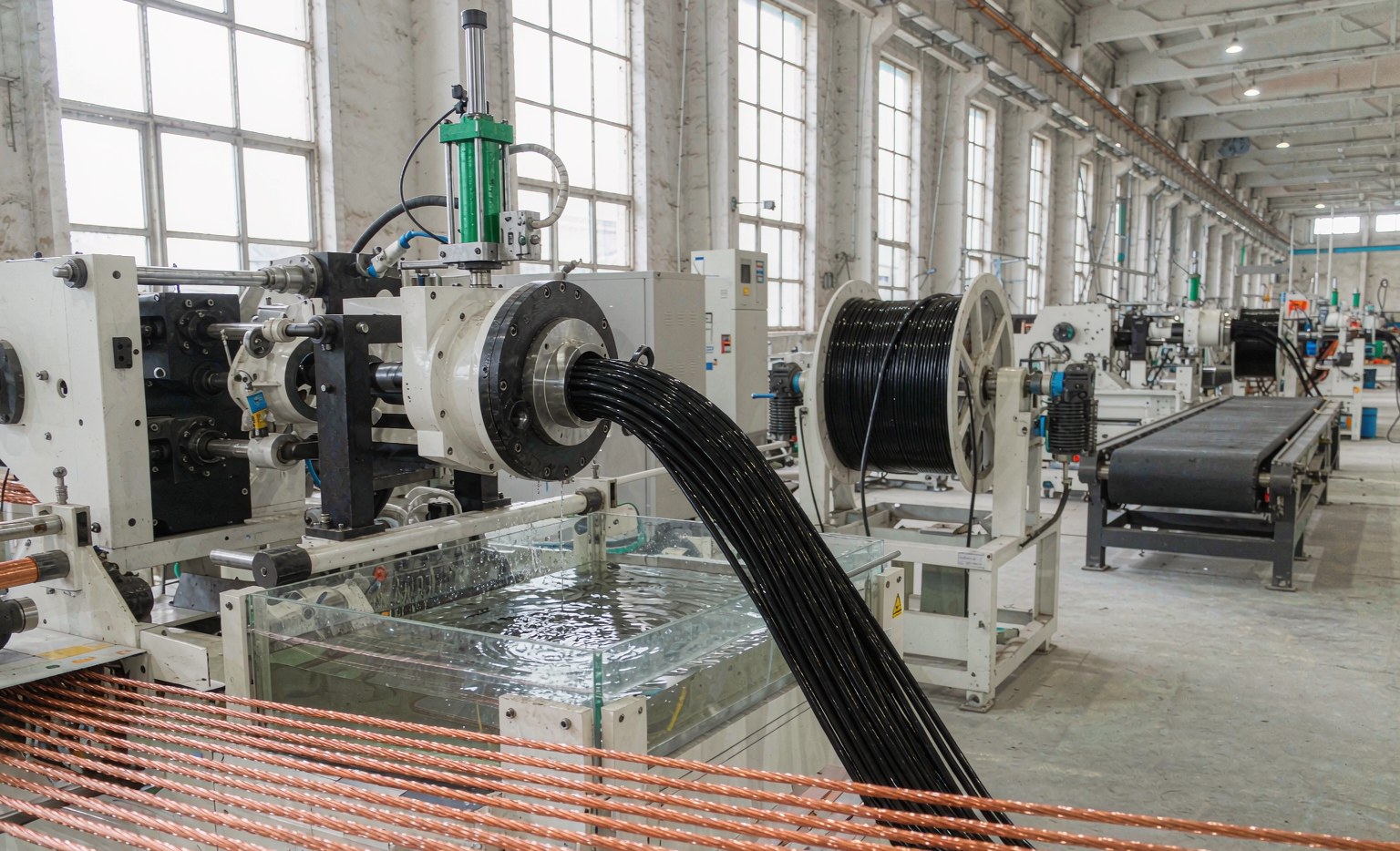
- Jacket extrusion — the outer PUR/TPE or PVC sheath is applied.
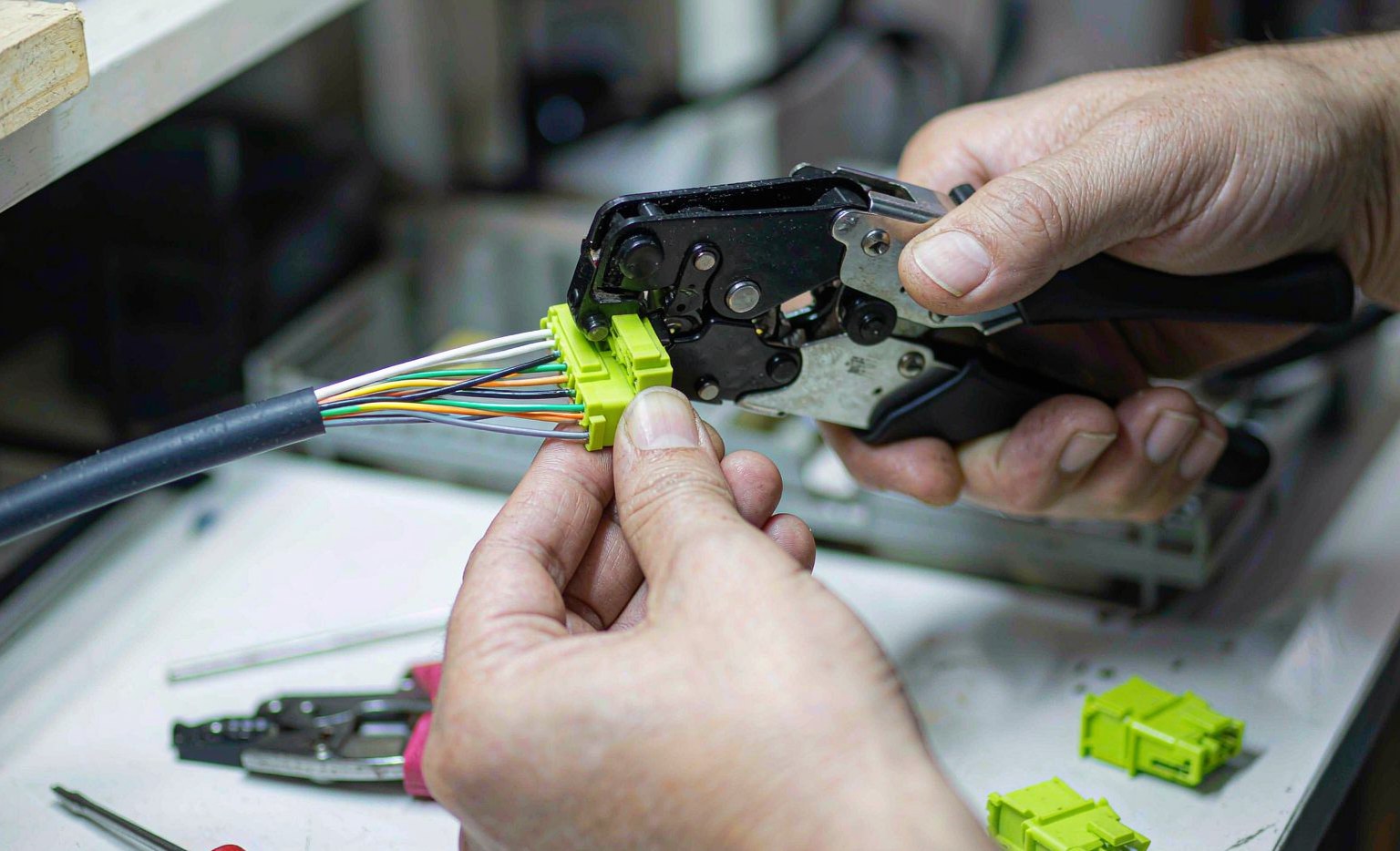
- Cutting, stripping and termination — conductors are exposed and crimped or soldered into the connector; crimp quality directly determines contact resistance.
- Injection moulding — an over-moulded boot is formed at the connector-to-cable junction, the single most important feature for strain relief. USB-C assemblies that require an E-Marker must have the programmed chip soldered before this step.
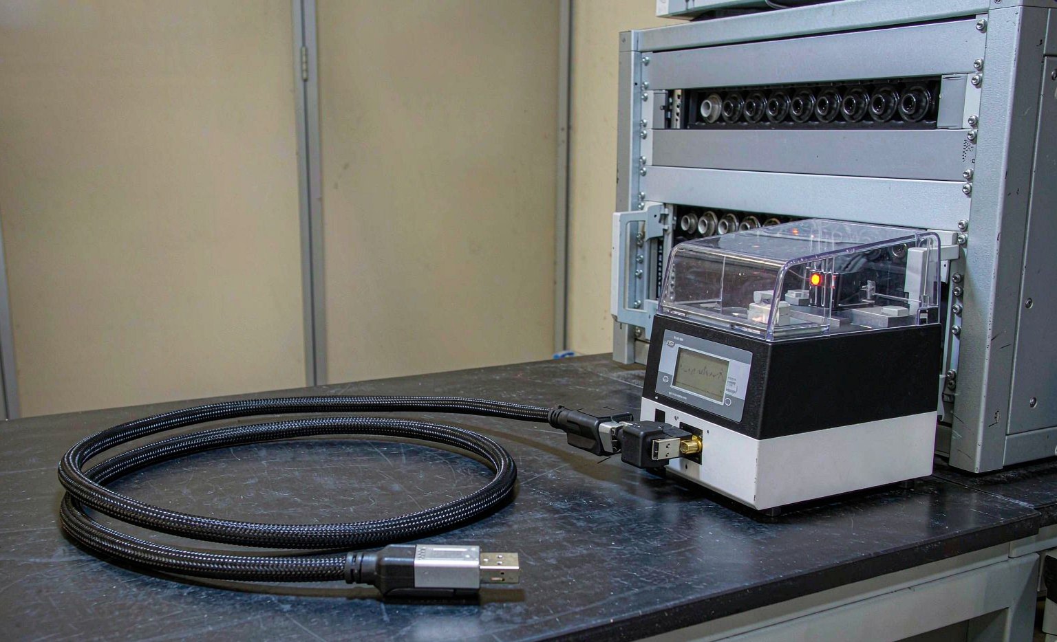
- 100% final test — every finished cable, not a sample, is electrically verified.
What a “100% tested” cable is actually tested for
| Test | What it catches |
|---|---|
| Continuity / wiring | Opens, shorts, swapped or misaligned pins |
| DC resistance | Undersized or non-copper conductors, high crimp resistance |
| High-voltage insulation (hi-pot) | Insulation breakdown between conductors and shield |
| Impedance / insertion loss (TDR) | Impedance mismatch, reflections, out-of-spec high-speed performance |
| E-Marker read-back | Wrong or counterfeit chip, incorrect current/voltage rating |
| Flex and insertion/extraction force | Strand fatigue, retention below specification |
For high-speed assemblies, impedance is the headline number. A 12 Gbps internal MiniSAS cable, for example, is specified at 100 Ω differential impedance; maintaining a tolerance as tight as ±5.2 Ω is what prevents signal reflection — the same discipline that a compliant industrial USB 3.x assembly needs (SFF-8643 vs SFF-8087 technical guide).
Standards and certifications to ask for
For a cable that will be installed in machinery, the relevant documentation is a combination of a signal standard and a safety/environmental standard set:
- Signal: USB-IF compliance for the speed grade claimed (USB Implementers Forum).
- Assembly workmanship: IPC/WHMA-A-620 for crimped and soldered cable assemblies.
- Electrical safety: IEC 62368-1 / EN 62368-1.
- Materials: RoHS and REACH; California Proposition 65 where the product ships to the US.
- EMC: FCC Part 15 and EN 55032 for the cable-plus-device system.
- Quality system: ISO 9001 (quality) and ISO 14001 (environment).
These are not interchangeable. A cable can pass continuity testing and still fail a hi-pot or an impedance check; conversely, a cable with excellent impedance control can fail RoHS on the jacket compound.
Specifying a custom cable: a six-point checklist
- Speed grade and length — state the protocol (USB 2.0 / 3.2 Gen 1 / Gen 2 / USB4) and the finished length; confirm it is inside the passive limit or specify active/optical.
- Retention class — match the retention force to the vibration environment, and confirm the host port has the threaded standoffs a screw-lock needs.
- Jacket and flex life — PUR or TPE for oil, abrasion and drag-chain duty; ask for the flex-cycle rating, because retention and flex life are different properties.
- Connector configuration — straight or right-angle over-mould, panel-mount feedthrough, or an M12 X-coded to USB adapter for sealed cabinets.
- Electrical targets — conductor gauge, differential impedance and tolerance, and the maximum permissible DC resistance.
- Certification and traceability — product certifications plus a per-batch test record, not just a catalogue claim.
Frequently asked questions
Can I use a screw-lock USB-C cable in a normal USB-C port?
Yes, it will plug in and work electrically. The screws only add retention if the host has matching threaded standoffs; otherwise they simply turn. For a laptop or hub without standoffs, choose a latching variant instead.
Why does my USB 3.0 camera cable work at 1 m but fail at 5 m?
Almost always cable length versus speed grade. Passive USB 3.2 Gen 1 copper is limited to roughly 3 m; beyond that, attenuation and impedance mismatch cause errors rather than a graceful slowdown. Use an active extension or a fibre/Cat extender.
What is the difference between an internal MiniSAS cable and an industrial USB cable?
Both are impedance-controlled shielded assemblies, but they serve different links. MiniSAS/SFF-8643 links storage inside a chassis; industrial USB links cameras, PLCs and instruments, and adds retention hardware that an internal cable does not need.
Do I need an E-Marker for a USB-C cable?
For USB-C cables rated above 3 A or supporting higher-speed data, yes. The E-Marker identifies the cable’s current and data capability to both ends; a missing or incorrect marker can limit charging or cause devices to negotiate unsafely.
Working with a cable manufacturer
Dongguan Longkai Electronics has manufactured high-speed data cables and connectors since 2012, operating a 3,000 m² facility with automated extrusion, braiding and assembly lines and an ISO 9001 / ISO 14001 quality system. Beyond catalogue items we build to drawing — custom lengths, panel-mount feedthrough assemblies and locking variants — with every assembly electrically tested before shipment. Browse the industrial cable range, the cable assembly range, or contact our engineering team with your specification.
Last updated: September 2026. Specifications follow the published USB-IF, IEC and IPC/WHMA-A-620 requirements; always confirm the passive length limit against the exact speed grade and cable construction of your assembly.