Every cable has a minimum bend radius, and every installation violates it. The violation is rarely deliberate: it happens when a cable is routed around a tight corner, coiled for storage, or pulled through a panel with no service loop. The consequences are cumulative and invisible until they are not — impedance changes that show up as intermittent errors, conductor fatigue that shows up as failures months later, and shielding damage that shows up as noise nobody can trace. This guide covers what bend radius actually does, how to specify it so installers can comply, and the field habits that protect it.
What Bending Does to a Cable
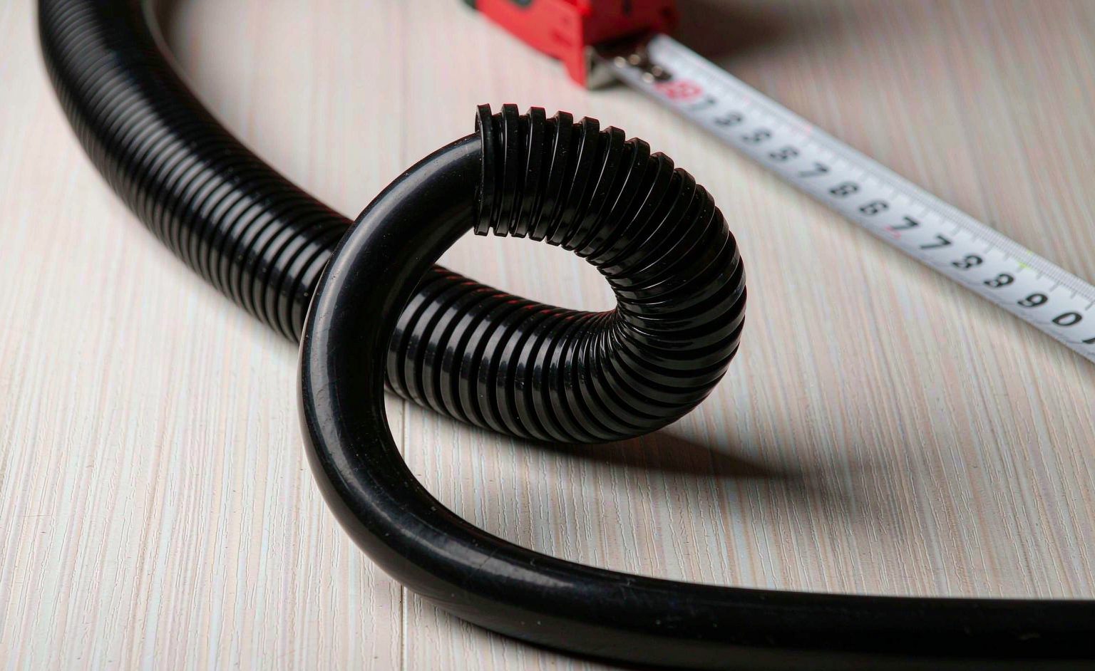
A cable bent below its minimum radius is deformed in three ways at once, and each matters to a different property. Geometrically, the conductors on the inside of the bend compress while those on the outside stretch — and in twisted-pair constructions, that deformation changes the pair’s geometry, which changes its impedance. Electrically, impedance discontinuity at the bend reflects signal energy, degrading the very margins high-speed cables are engineered to hold. Mechanically, repeated flexing at an over-tight radius fatigues the conductors and the shield, and the failure arrives later, far from the bend that caused it.
| Effect | Mechanism | Observable consequence |
|---|---|---|
| Impedance change | Pair geometry deformed | Reflections, eye-closure, intermittent errors at high speed |
| Conductor fatigue | Repeated flex at tight radius | Opens or high-resistance joints, months later |
| Shield damage | Foil braid stress, braid distortion | EMI susceptibility; noise correlated with cable movement |
| Jacket stress | Compression and stretch cycles | Jacket cracking; moisture ingress follows |
The signal-integrity mechanism is the one that costs the most to diagnose, because the symptoms appear at the system level — error counts, dropped links — and the cause sits in a cable run nobody suspects. The relationship between cable construction and signal behaviour is developed in our signal integrity guide, and the failure patterns that tight bends contribute to in our cable failure diagnostic guide.
How to Read and Specify Bend Radius
Minimum bend radius is specified either as a fixed dimension or as a multiple of the cable’s outer diameter, and the two are not interchangeable. A “8× OD” specification scales with the cable; a fixed 40 mm specification does not. The distinction matters when a program offers multiple lengths or gauges, because a spec written for one construction silently invalidates itself when the diameter changes. The specification should also distinguish static bend radius (installed, not moving) from dynamic bend radius (flexing in service, e.g. cable tracks), because dynamic applications demand a larger radius and a flex-rated construction.
| Context | Typical requirement | Specification note |
|---|---|---|
| Fixed installation | Static minimum, often 4–8× OD | Verify against the manufacturer’s figure, not habit |
| Occasional movement | Between static and dynamic | State the motion profile, not just “flexible” |
| Continuous flexing | Flex-rated construction, larger radius | Different cable family entirely; cycle-rated |
| Pre-terminated assemblies | Set by the weakest point: connector exit | Strain relief governs, not the cable |
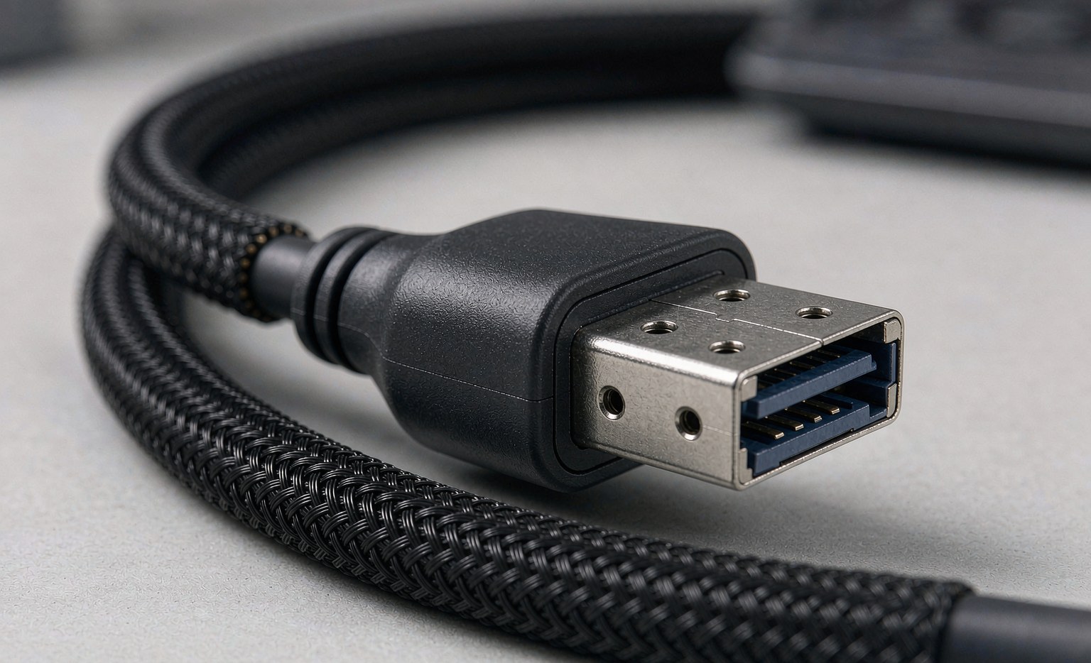
The last row catches most assembly buyers: in a terminated cable, the practical bend limit is usually at the connector’s strain relief, not in the cable body. An assembly specified with a generous cable bend radius but a tight strain-relief exit will fail at the exit first. The design factors that govern this are covered in our custom cable assembly design guide and our reliable high-speed assembly guide.
Making the Spec Survive the Installation
A bend-radius specification that exists only on the drawing fails on the first install. The practices that make it survive: provide service loops at both ends so field terminations can be remade without re-pulling the run; specify cable carriers or conduit where runs must turn tightly; label the minimum bend radius on the cable itself at intervals, so the installer holding the cable sees the number; and design the routing so the tightest corner exceeds the spec with margin — a layout that just meets the spec will be violated by the first technician who is in a hurry.
For high-speed assemblies, one more practice pays for itself: verify the installed run, not just the spec. A quick time-domain check on a sample installation catches the impedance discontinuity that a tight bend introduced, before it becomes an intermittent field failure nobody can reproduce. The verification discipline mirrors the cable-performance testing covered across our assembly guides — the cheapest place to find a bend-radius problem is at acceptance, not at the customer site.
Frequently Asked Questions
What is a safe default bend radius?Use the manufacturer’s figure for the specific cable — but as a rule of thumb, never below roughly 8× the outer diameter for fixed installs, and substantially more for anything that moves.
Does a one-time tight bend during installation matter?It can, permanently. A single over-tight bend deforms pairs and shields in ways that persist; if it happens, replace the section rather than hoping the error rate stays acceptable.
Why do cable tracks need special cable?Continuous flexing at millions of cycles is a fundamentally different duty; flex-rated constructions with specified cycle life and dynamic bend radius exist precisely for it, and standard cable will fatigue regardless of its static rating.
Technical background: {{OUT:https://en.wikipedia.org/wiki/Bend_radius|bend radius fundamentals}}, {{OUT:https://en.wikipedia.org/wiki/Twisted_pair|twisted-pair geometry}} and {{OUT:https://en.wikipedia.org/wiki/Characteristic_impedance|characteristic impedance}} cover the engineering concepts referenced above.