USB-C ocupa los titulares, y con buenas razones. Pero si entras en una fábrica, en una sala de equipos médicos o en un depósito de servicio en campo, la población de conectores se ve muy diferente. Los controladores lógicos programables comisionados hace una década aún presentan puertos de servicio Mini-USB. Los escáneres de mano, las cámaras antiguas, las unidades de GPS y una larga cola de instrumentos de medición aún se envían con Micro-USB. Las máquinas más nuevas en la misma línea de producción ejecutan USB-C. Alguien tiene que mantener los tres vivos, y esa persona suele ser quien escribe la especificación del cable.
Esta guía está escrita para esa persona. Compara Mini USB, Micro USB y USB-C en los atributos que deciden una decisión de adquisición: retención mecánica, capacidad de datos, capacidad de potencia y lo que sucede cuando el entorno se vuelve hostil; y utiliza figuras publicadas en la documentación técnica del propio fabricante en lugar de copias de marketing genéricas.
Por qué los conectores legados siguen siendo un problema de ingeniería
El instinto al enfrentar una cartera mixta de conectores es estandarizar en USB-C y terminar con eso. En la práctica, eso rara vez es posible en un solo paso, y la razón no es el conservadurismo. Es que el conector es parte de un ensamble certificado. Cambiar el puerto de servicio en un dispositivo médico o en una pieza de equipo industrial puede activar la reevaluación de toda la unidad, no solo del puerto. El cable es barato; la recertificación no.
El resultado es un período largo de superposición donde tres generaciones de conectores coexisten en el mismo sitio. Esa superposición es manejable si está planificada. Se convierte en costosa cuando se descubre, típicamente de una de dos formas: un ingeniero en campo llega con el cable incorrecto y el trabajo se reprograma, o un comprador ordena “cables USB” al por mayor y recibe ensambles que son físicamente correctos pero eléctricamente incorrectos para la aplicación.
El segundo fallo es el más insidioso, porque se ve como un éxito hasta que se instala. Un cable que se acopla perfectamente aún puede estar limitado a velocidades USB 2.0 y carga lenta, y la guía técnica publicada sobre este punto es contundente: dos cables pueden verse idénticos mientras su cableado interno difiere completamente. Algunos solo admiten 480 Mbps y carga lenta; otros son ensambles de funciones completas que transportan video 4K, datos de 10 Gbps y carga de 100 W en la misma funda.
Las tres familias de conectores, y de dónde vino cada una
Comprender la genealogía ayuda a predecir el comportamiento en el campo.
Las familias Mini y Micro pertenecen a la era de USB 2.0. USB 2.0 se lanzó en 2000 y ofreció una tasa de transferencia de alta velocidad de 480 Mbps, más de cuarenta veces más rápida que su predecesora, con alimentación de hasta 2,5 W. Eso fue suficiente para hacer que los discos duros externos, las cámaras web y los escáneres fueran verdaderamente prácticos, y estableció la población de conectores que sigue en servicio hoy en día: el rectangular plano USB-A para dispositivos más grandes como impresoras, y los conectores más pequeños para equipos portátiles. En la guía de aplicaciones publicada, los cables USB mini se asocian con dispositivos que requieren un conector más pequeño, como cámaras antiguas y unidades GPS, mientras que los cables USB micro se asocian con dispositivos más pequeños, como teléfonos inteligentes y tabletas.
El siguiente cambio de etapa llegó con USB 3.0, introducido en 2008 y posteriormente rebautizado como USB 3.1 Gen 1, que trajo el protocolo SuperSpeed a un máximo teórico de 5 Gbps. Esto se logró añadiendo cables internos para permitir la comunicación full-duplex, y los puertos solían ser de color azul para distinguírselos. De manera crucial, USB-A fue diseñado para ser compatible hacia atrás, que es la razón por la que el ecosistema transitó tan suavemente como lo hizo.
USB-C es el punto final actual de esa línea. Es un sistema de conector físico construido alrededor de un diseño de doble cara de 24 pines, lo que lo hace reversible: no hay arriba ni abajo. La documentación de productos publicada señala que es aproximadamente del tamaño del enchufe Micro-USB más antiguo, pero que es mucho más capaz, y que un ensamblaje de alta calidad único puede transportar datos, energía y video simultáneamente.
Tabla de comparación: Mini USB frente a Micro USB frente a USB-C
La tabla siguiente compara las tres familias en los criterios que deciden una compra. Las celdas que dependen del ensamblaje específico más que de la familia de conector se marcan como dependientes del ensamblaje, porque es donde se cometen la mayoría de los errores de adquisición.
| Criterio | Mini USB | Micro USB | USB-C |
|---|---|---|---|
| Era y estándar de origen | Era de USB 2.0 | Era de USB 2.0 | Generación actual, doble cara de 24 pines |
| Orientación | Direccional | Direccional | Reversible, sin arriba ni abajo |
| Tamaño relativo | Más pequeño que USB-A | Más pequeño que USB-A; USB-C es aproximadamente de este tamaño | Delgado, ovalado |
| Dispositivos host típicos | Cámaras antiguas, unidades GPS, puertos de servicio legacy | Teléfonos inteligentes, tabletas, dispositivos portátiles más pequeños | Portátiles nuevos, cámaras industriales, sistemas de visión por máquina |
| Capacidad de datos | Depende del ensamblaje; los ensamblajes de clase USB 2.0 funcionan a 480 Mbps | Depende del ensamblaje; los ensamblajes de clase USB 2.0 funcionan a 480 Mbps | Depende del ensamblaje; documentado hasta 10 Gbps o 20 Gbps en ensamblajes capaces |
| Capacidad de energía | Nivel legacy, coherente con el perfil de 2,5 W de USB 2.0 | Nivel legacy | USB Power Delivery de hasta 100 W, y hasta 240 W con el último estándar EPR |
| Salida de video | No aplicable | No aplicable | Sí en ensamblajes capaces; video 4K documentado |
| Retención bajo vibración | Solo fricción; una debilidad conocida en equipos en movimiento | Solo fricción | Solo fricción a menos que se especifique una variante de bloqueo |
| Estado de adquisición | Legacy; planificar por obsolescencia | Legacy; aún tiene amplia existencias | Predeterminado actual para nuevos diseños |
Lo que realmente falla en el campo
Las fallas de conectores en entornos industriales se agrupan en tres patrones, y rara vez se deben a que el cable se rompa limpiamente por la mitad.
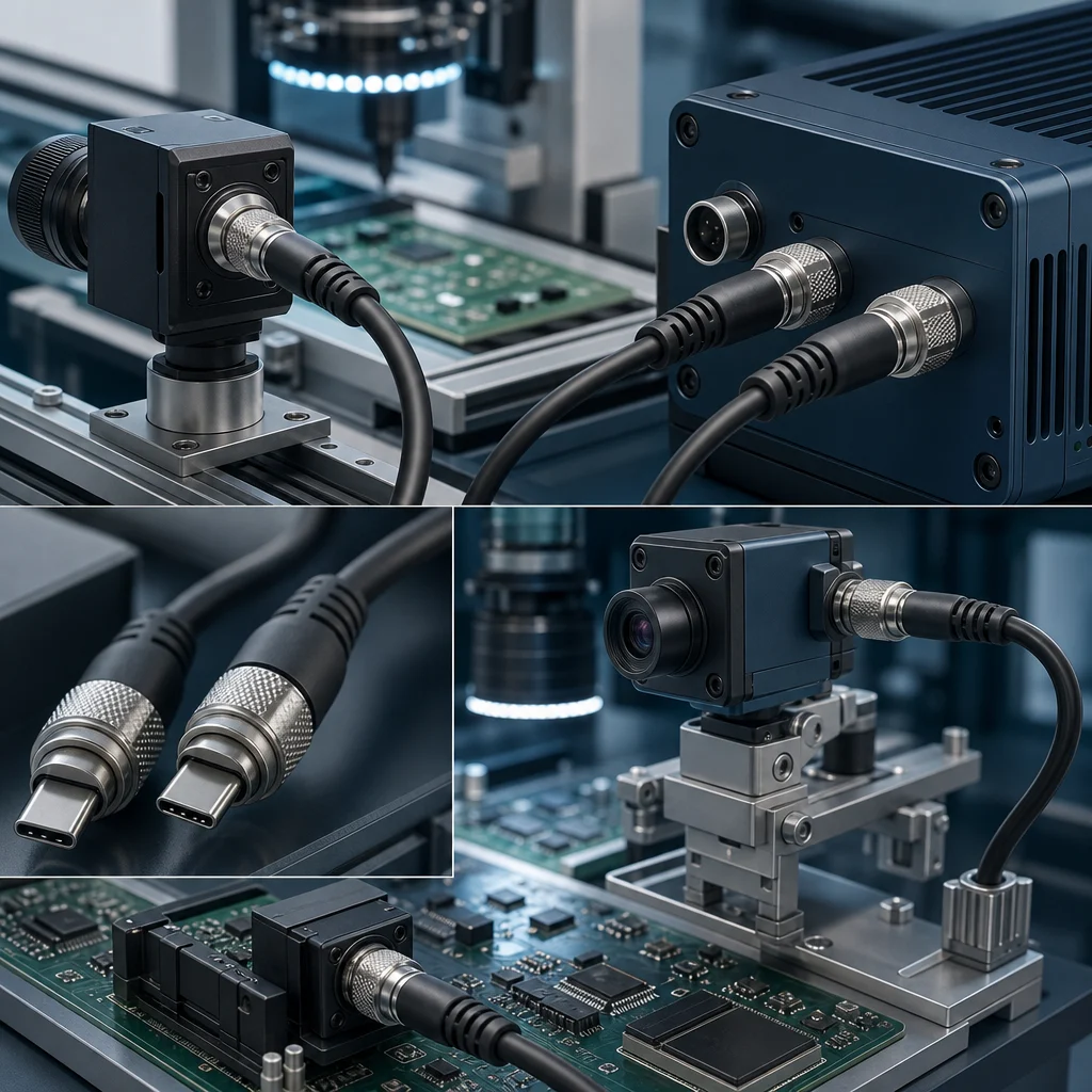
The first is retention. A friction-fit connector in a vibrating cabinet walks out over time. Published guidance on industrial USB-C is explicit that standard connectors can vibrate loose in factory settings, and that the mitigation is a locking design: connectors with single or dual screw locks on the housing, which bolt securely into the port and hold a stable connection for industrial cameras and machine vision systems even under intense vibration. If your equipment moves, this is not an optional upgrade.
The second is electrical mismatch. The connector mates, the device charges slowly or enumerates at the wrong speed, and nobody can see the problem because the physical layer looks fine. This is the failure mode behind the warning that a low-quality cable on a high-end device will bottleneck its performance. The specification fix is to state the required data rate and power level on the purchase order and require the supplier to confirm the assembly meets it, rather than ordering by connector shape.
The third is contamination and mechanical wear at the port. Legacy connectors on older equipment have often been mated hundreds of times by staff who were not thinking about connector life. By the time a replacement cable is ordered, the port on the device may be the real problem. A good diagnostic routine checks the device port before blaming the cable, and a good supplier will ask about the port condition rather than simply shipping a replacement.
A structured approach to these failure patterns, including how to isolate whether the fault sits in the cable, the connector or the port, is set out in the diagnostic guide to common cable failures.
Matching Power and Data to the Application
The numbers that matter are not the headline maximums. They are the values your device actually needs, stated clearly enough that a supplier can confirm or decline them.
On power, the scale runs from the legacy USB 2.0 profile of up to 2.5 W, through the typical 2.5 W to 5 W output of a standard USB-A port, to USB Power Delivery on USB-C at up to 100 W, and up to 240 W under the latest EPR standard. A single USB-C assembly at the high end can charge a phone, a tablet and a powerful laptop. If your application is a handheld scanner that trickle-charges overnight, specifying a 100 W assembly is waste without benefit; if it is an industrial camera drawing real power over the same cable, underspecifying is a field failure waiting to happen.
On data, the practical ladder runs 480 Mbps for USB 2.0 class work, 5 Gbps for SuperSpeed, and 10 or 20 Gbps on capable USB-C assemblies. Transferring configuration files to a legacy controller needs the first rung. Streaming uncompressed video from a machine vision camera does not. The mistake is assuming the connector implies the speed — it does not, and the documented example is stark: some USB-C cables support only USB 2.0 speeds and slow charging while others are full-featured.
There is a compliance dimension here too. A poorly made USB-C cable can draw too much power and damage the device it is connected to, which turns a five-dollar saving into a four-figure replacement. Certifications to look for on the supplier side include ISO 9001 and ISO 14001 for the manufacturing system, and CE and FCC compliance for the product.
Four Realistic Migration Paths
Once the estate is mapped, migration usually resolves into one of four patterns.
- Adapter bridging. The fastest fix for a mixed estate, connecting an existing USB-A or legacy device to a newer USB-C port. It solves today’s problem and adds a mechanical joint, so it suits bench and service environments rather than permanently vibrating installations.
- Hybrid assemblies. A single cable with a legacy connector at one end and USB-C at the other, built to a defined specification. This removes the adapter from the chain and is usually the right answer for equipment that is being kept but re-cabled.
- Locking USB-C retrofit. Where the device already has USB-C but the environment is hostile, moving to a screw-locking assembly addresses the retention failure without touching the device certification. This is the common pattern for industrial cameras and machine vision.
- Full redesign. Appropriate at end-of-life or when the device is being re-certified anyway. It is the most expensive path and the only one that removes the legacy connector from the bill of materials entirely.
The sequencing matters more than the choice. Standardising new purchases on USB-C while keeping a documented stock of legacy assemblies for installed base is usually cheaper than any forced conversion, and it avoids the trap of re-certifying equipment purely to retire a port.
Sourcing Checks Before You Commit
Five questions, asked before the purchase order, prevent most of the problems described above.
First: what data rate and power level must the assembly actually carry? Get it in writing on the order. Second: is a locking variant required? If the equipment vibrates, friction retention is not sufficient. Third: which certifications apply to your market and does the supplier hold them — ISO 9001 and ISO 14001 for the manufacturing system, CE and FCC for the product. Fourth: is the assembly full-featured or charge-only? The connector shape will not tell you. Fifth: what is the plan for the legacy end of the estate, and is the supplier able to support both generations rather than only the current one?
Manufacturer track record is worth weighing alongside the specification. Longkai Electronics, which has been producing cable assemblies since 2012 and supplies consumer and industrial customers including LG and CATL, publishes ISO 9001 and ISO 14001 certification and CE and FCC product compliance, with over 100 global partners — the kind of documentation that makes the certification answers quick and verifiable rather than promotional.
For the underlying standards background, the evolution of USB from a simple port to a universal powerhouse traces how each generation solved the problems of its time, and the USB-C explainer covers the connector’s power, data and video capability in detail.
Preguntas frecuentes
Are Mini USB and Micro USB the same connector?
No. They are distinct connector families from the same USB 2.0 era, and they are not interchangeable. Published application guidance associates Mini USB with devices needing a smaller connector such as older cameras and GPS units, and Micro USB with smaller devices such as smartphones and tablets. Check the device port before ordering rather than assuming.
Can I replace a Mini USB cable with a USB-C cable?
Not directly, because the connectors are physically different. The practical options are an adapter, a hybrid assembly with a legacy connector at one end and USB-C at the other, or a device-side port change — and the third option can trigger re-certification of the whole unit.
Why does my USB-C cable charge slowly when the connector fits perfectly?
Because the connector shape does not determine capability. Documented guidance notes that two physically identical cables can differ internally, with some supporting only USB 2.0 speeds and slow charging while others are full-featured assemblies carrying 4K video, 10 Gbps data and 100 W charging. Specify the required rate and power level explicitly.
What should I specify for equipment that vibrates?
A locking connector. Standard USB connectors can vibrate loose in factory settings; screw-locking USB-C assemblies with single or dual screws on the housing bolt into the port and maintain a stable connection for industrial cameras and machine vision systems under intense vibration. Full design considerations are covered in the field engineer’s guide to screw-lock USB-C design.
How much power can USB-C actually deliver?
USB Power Delivery on USB-C reaches up to 100 W, and up to 240 W under the latest EPR standard. For comparison, standard USB-A ports typically output 2.5 W to 5 W, and the legacy USB 2.0 profile was up to 2.5 W. Match the rating to the device rather than defaulting to the maximum.
Planning the Overlap Rather Than Fighting It
The connector estate on a real site is an artefact of procurement history, not a design choice, and the goal is to manage it rather than to eliminate it on a schedule. Map what you have, state data and power requirements explicitly on every order, specify locking connectors wherever equipment moves, and standardise new purchases on USB-C while keeping documented legacy stock for the installed base.
That approach costs less than forced conversion and avoids re-certifying equipment just to retire a port. It also puts the specification in the right place: on the purchase order, where a supplier can confirm it or tell you it is not achievable, instead of in a complaint after the cable has been installed.