Of everything that can go wrong in a cable assembly, the crimp is the failure most likely to reach the field and least likely to be caught by electrical test. A joint that passes continuity and hipot can still be under-crimped, over-crimped, or formed with a wrong wire and terminal combination, and from outside it is indistinguishable from a good one. The consequences arrive later as intermittent contact, heating under load, or a terminal backing out of its housing.
Cross-section analysis is what makes the difference visible. Sectioning a crimped terminal, polishing the cut face and examining it under magnification is the only method that shows what actually happened to the conductor strands inside the barrel. This article covers what a good crimp looks like, how a section is read, and what a buyer should ask the assembler to produce.
Why the Crimp Decides Field Reliability
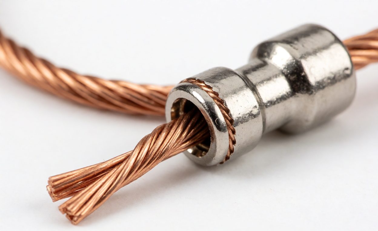
A crimp is a cold-formed gas-tight joint. The barrel is compressed around the stripped conductor so that the strands deform, fill the barrel voids and press against the wall with enough residual force to keep the interface oxide-free for the service life of the product. There is no metallurgical bond; integrity comes from controlled plastic deformation and elastic spring-back.
That mechanism explains the failure modes. Too little compression leaves voids between strands, current crowds through a reduced section, and the joint runs hot while retention stays weak. Too much compression work-hardens the barrel, severs strands and cracks the plating. Either error can test electrically perfect at the bench and fail in service.
What a Good Crimp Is Supposed to Do
Judge a crimp against four requirements, all of them measurable:
- Gas-tight contact. Strands and barrel deformed enough that the interface excludes air and moisture over the product life.
- Full strand capture. Every strand inside the barrel, none splayed outside the crimp zone or left uncompressed.
- Tensile retention. The joint holds the pull force specified by the terminal maker for that wire size.
- Insulation support. Where there is an insulation barrel, it grips the jacket without cutting in, so bend forces never reach the conductor crimp.
Each is a process outcome rather than a design feature, which is why crimp control cannot be verified by looking at the finished assembly.
Reading a Cross-Section
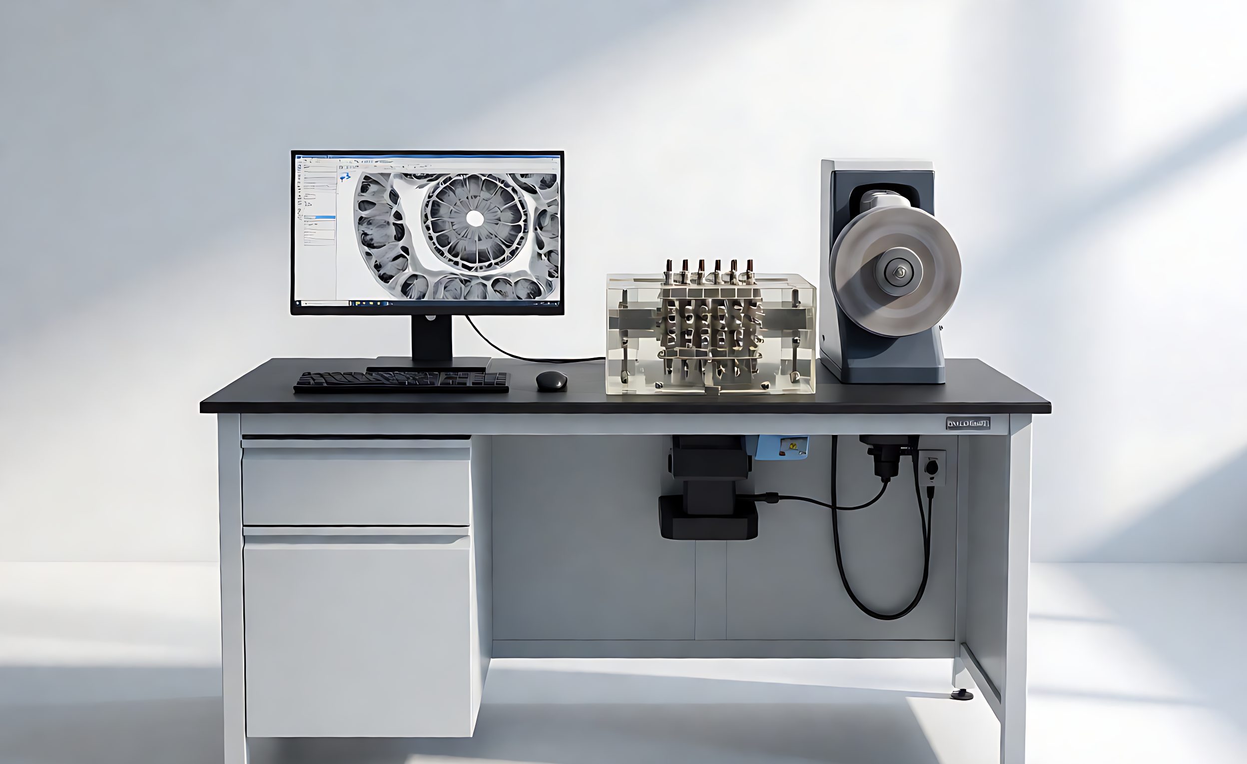
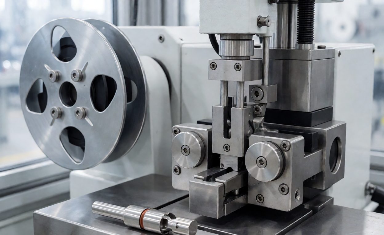
Preparation matters as much as interpretation. The sample is potted in resin, cut through the center of the crimp, then ground and polished to show individual strand boundaries. A poorly prepared sample smears copper across the face and hides exactly the voids the analysis exists to find.
On a good section the barrel is symmetrical with the seam closed, the strands fill the available area with only small interstices, and there is no continuous gap at the interface. Compression is a ratio of compressed to original conductor area, and most makers publish a target band per wire size.
The common findings are recognizable. Large voids between strands indicate under-compression, usually a crimp height set too high or a worn die. A barrel stretched thin at the corners indicates over-compression. A conductor sitting off-center points to a strip-length error or incomplete insertion. Each finding maps back to one machine setting.
Pull Force and What It Does Not Prove
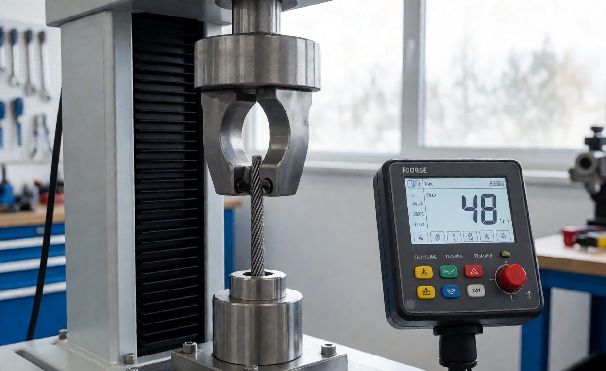
Pull testing is the routine companion to cross-section work. The conductor is pulled axially at a controlled rate until it separates from the terminal or the wire breaks, and the force is compared with a published minimum for the terminal and wire combination. It is cheap, fast and suitable for sampling through a run.
Its limitation is that it is a single-point mechanical result: a crimp can meet the pull minimum while having poor compression. Pull force shows the joint is not weak, not that it is sound. Used together the two complement each other – pull testing catches drift between section checks, and sectioning explains what that drift did.
Technical Background
The joining method is crimping, whose quality depends on the plastic deformation of conductor and terminal. Examining a polished cut face is a branch of metallography, and the mechanical check is a form of tensile testing on the termination.
Holding Crimp Quality in Production
Crimp quality is a process capability problem, and the controls that work are the ordinary ones applied consistently:
- Qualify the combination. Wire, terminal and tool must be qualified together; a terminal approved with one stranding behaves differently with another.
- Set and log crimp height. Crimp height, not machine pressure, is the controlled variable, measured at setup and at defined intervals.
- Use the specified tooling. Applicators matched to the terminal family, dies within service life, and a calibration record behind the tool.
- Check operators, not only machines. Strip length, full insertion and handling before the crimp closes drive much of the defect rate.
- Section on a schedule. A section at setup and at intervals through the run catches drift that pull testing will not characterize.
- Retain the samples. Kept sections and pull records make a field return analyzable.
What Buyers Should Require
Four items belong in a purchase specification for crimped assemblies: the terminal and wire combination qualified, the crimp height or compression target with its tolerance, the pull-force minimum per wire size, and the inspection frequency with the records to be delivered. Where service life is critical, require periodic cross-section reports.
At first article and at goods-in, ask for the setup section and the pull-test record for each wire size. Both are inexpensive to produce and impossible to reconstruct later. Those expectations sit alongside the test report buyers should require and feed failure analysis and field returns. They are also the basis of PPM defect rate targets and of the drawing-to-sample-to-bulk-production process.
Часто задаваемые вопросы
What is a crimp cross-section analysis?
The terminal is potted in resin, cut through the crimp, polished and examined to measure compression and check for voids.
Why can a bad crimp still pass electrical testing?
Continuity and hipot only prove a conducting path exists, not that the joint is compressed correctly.
What is crimp height?
The measured height of the compressed barrel, set per wire and terminal combination as the controlled variable.
Is a pull test enough to verify crimp quality?
No. Pull force shows the joint is not weak but says little about compression.
What does an under-crimped joint look like in section?
Large voids between strands, a rounded barrel with an open seam, and reduced contact area.
Can over-crimping be as bad as under-crimping?
Yes. Over-compression severs strands, cracks the barrel and damages the plating.
What should a buyer ask the assembler to provide?
Setup cross-sections with images, pull-test records per wire size, crimp height logs and the inspection frequency, all named in the specification.