In a consumer application a USB cable is specified for bandwidth. In an industrial application it is specified for whether it stays connected. Machine vision cameras, motion controllers and factory equipment subject the connector to vibration, flexing and repeated mating, and a standard friction-fit connector eventually works loose — producing the intermittent link drop that is hardest to diagnose and most expensive in downtime. Locking is the answer, but it is only one of four parameters that decide reliability. This guide covers the selection.
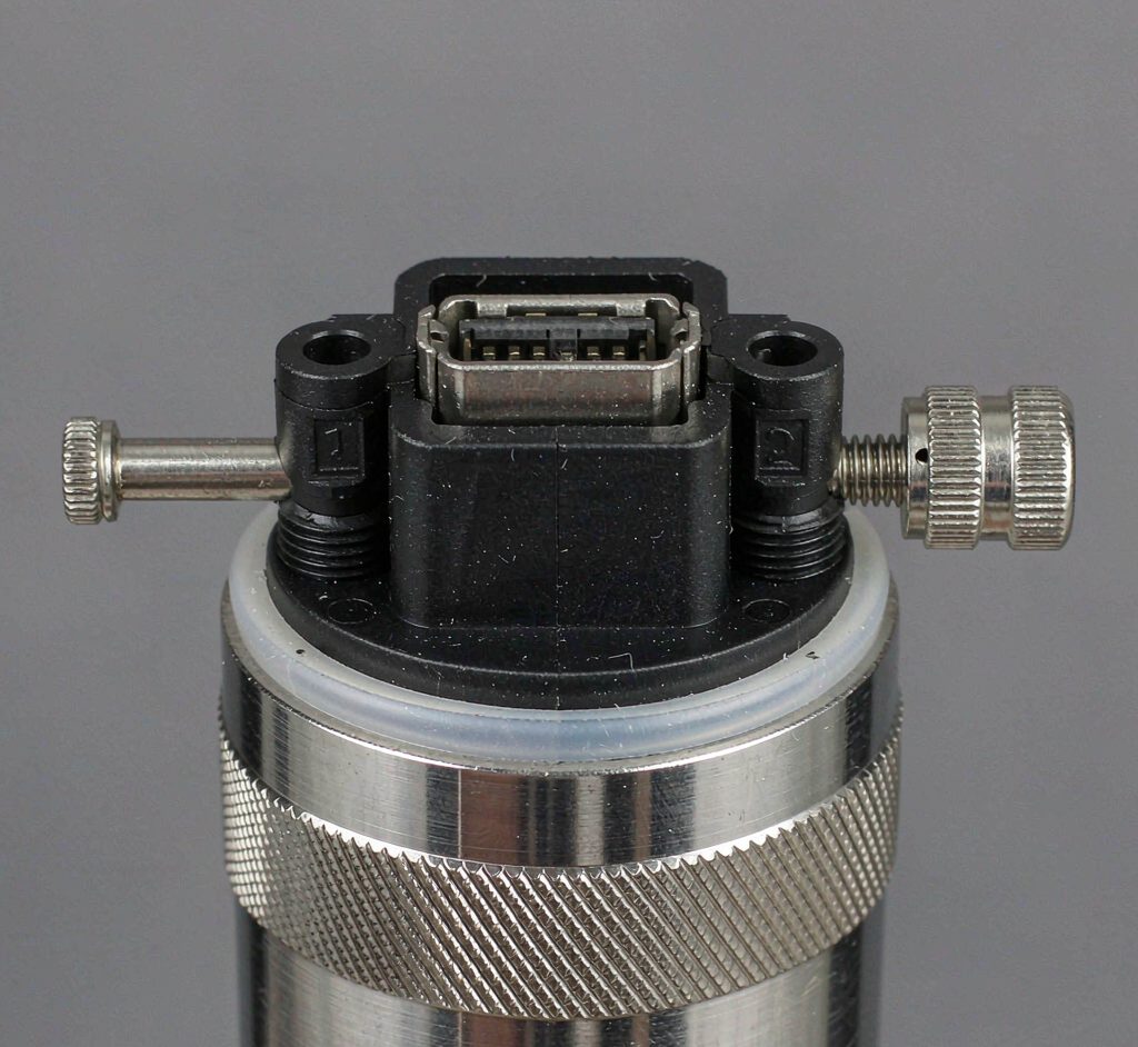
Key Takeaways
- Industrial cable selection is about staying connected, not about bandwidth.
- Locking mechanism must match the mating port; visual similarity is not compatibility.
- Gauge and flex life decide whether the cable survives movement, not just vibration.
- Strain relief is what prevents the port joint from failing under cable movement.
- Intermittent link drops are a mechanical symptom, not an electrical one.
The Four Selection Parameters
Four parameters decide whether an industrial USB cable works, and only one of them is electrical.
| Parâmetro | What it decides | O que especificar |
|---|---|---|
| Connector and locking | Whether the connection survives vibration | Connector part number plus locking type |
| Gauge and conductor count | Current capacity and flex life | AWG, conductor count, stranding |
| Jacket material | Abrasion, oil and chemical resistance | Jacket compound and its ratings |
| Strain relief and routing | Whether movement loads the port joint | Boot type, bend radius, exit direction |
The connector and locking row is where most ordering errors happen, because the same visual family contains multiple incompatible retention designs. Confirm against a photo of the actual mating port. The specification discipline is covered in our guide to specifying an assembly that delivers.
Locking Mechanisms Compared
Three retention approaches cover industrial USB, and they suit different applications.
| Mecanismo | How it works | Best for | Watch out for |
|---|---|---|---|
| Screw-locking | Captive screws clamp the connector to the port | High vibration, motion axes, mobile equipment | Slower mating; thread and standoff must match |
| Latch / clip | A spring latch engages a port feature | Moderate vibration, frequent mating | Latch geometry varies between vendors |
| Friction / guided | Held by connector fit alone | Static installations, no vibration | Works loose under any real movement |
Screw-locking is the specification to reach for where the equipment moves or vibrates, because it is the only mechanism that positively retains rather than relying on friction. The trade-off is mating time and the requirement that thread and standoff match the port exactly. The variants and their use cases are covered in our right-angle and screw-locking guide.
Flex Life and Routing
A cable that is correctly locked can still fail if it is too stiff for the motion it sees.
| Fator | Efeito | O que especificar |
|---|---|---|
| Conductor stranding | Fine stranding survives more flex cycles | Stranded rather than solid conductors |
| Calibre | Thicker gauge is stiffer and flexes less well | Thinnest gauge that meets the current requirement |
| Bend radius | Exceeding it fatigues conductors | Minimum bend radius and the routing that respects it |
| Continuous flex | Cable-tray and drag-chain duty is a different product | Whether continuous-flex construction is required |
Continuous-flex applications — drag chains, cable trays, moving axes — need a cable built for that duty, not a standard industrial cable with a locking connector. The two are different products and the difference is in conductor construction and jacket compound. The routing constraints are covered in our bend radius guide.
The Failure Modes Locking Prevents
Understanding the failure modes explains why the specification matters.
| Failure mode | Symptom | Root cause |
|---|---|---|
| Intermittent link drop | Connection drops under vibration, recovers at rest | Connector partially unmated; contact resistance rising |
| Port joint failure | Cable fails at the connector, conductors broken | Movement load transferred into the soldered joint |
| Contact wear | Increasing errors over months | Micro-motion at the contact interface |
| Jacket abrasion | Insulation damage in a specific spot | Routing against a moving surface |
The first row is the one that wastes the most engineering time, because it presents as an electrical or firmware problem when it is mechanical. A camera that drops frames only while the gantry moves is a cable problem. The connector durability factors behind these failures are covered in our USB-C connector durability guide.
Perguntas Frequentes
What is a screw-locking USB cable?
A cable whose connector has captive screws that clamp it to the mating port, providing positive retention under vibration rather than relying on friction.
When do I need a locking USB cable?
Wherever the equipment vibrates or moves — machine vision on moving axes, mobile equipment, factory floor installations. In static installations a friction-fit connector is usually adequate.
Are all locking USB connectors compatible?
No. Retention geometry, thread size and standoff height vary between vendors and even between product families. Confirm against a photo of the actual mating port.
Why does my camera drop frames only when the machine moves?
Almost always a partially unmated connector. It presents as an electrical or firmware problem but the root cause is mechanical: contact resistance rising under vibration.
Does gauge matter for a data cable?
Yes, in two ways: current capacity for powered devices, and flex life. Thicker gauge is stiffer and survives fewer flex cycles, so specify the thinnest gauge that meets the requirement.
Do I need a special cable for a drag chain?
Yes. Continuous-flex duty needs a cable built for it — fine-stranded conductors and a suitable jacket compound — not a standard industrial cable with a locking connector.
What is the most common industrial cable failure?
Failure at the connector, where cable movement has fatigued the conductors or the soldered joint. Correct strain relief and bend radius prevent it.
Technical background: USB, visão por máquina e mechanical vibration explain the interface, the application and the failure driver referenced above.