Ask an engineer where a cable assembly fails and the answer is rarely the wire. It is the point where the wire meets the connector, and specifically the transition zone between the flexible cable and the rigid shell. Every bend, every tug and every accidental yank concentrates stress in a few millimetres of material. The overmold exists to distribute that stress, and it is the cheapest part of the assembly to get right or wrong.
Most buyers specify connector type, wire gauge, length and colour, then accept whatever overmold the factory considers standard. That is how a cable rated for ten thousand bends in a datasheet arrives with a stiff boot that cracks at two thousand. This guide covers what the overmold does mechanically, how material choice changes the outcome, what geometry to specify, and which tests produce evidence rather than reassurance.
What the Overmold Actually Does
An overmold is not decoration. It performs four distinct jobs, and any of them can be the one that fails in the field.
- Strain relief: it grips the jacket and the connector body so that load transfers gradually instead of concentrating at the solder joint.
- Environmental sealing: it closes the gap between cable jacket and shell, which is where moisture and dust enter.
- Mechanical retention: it provides the surface a pull force acts on, and sets how much force the assembly survives before the connector separates.
- Identification and handling: colour, hardness and surface texture tell a user where to grip and how the cable is meant to be routed.
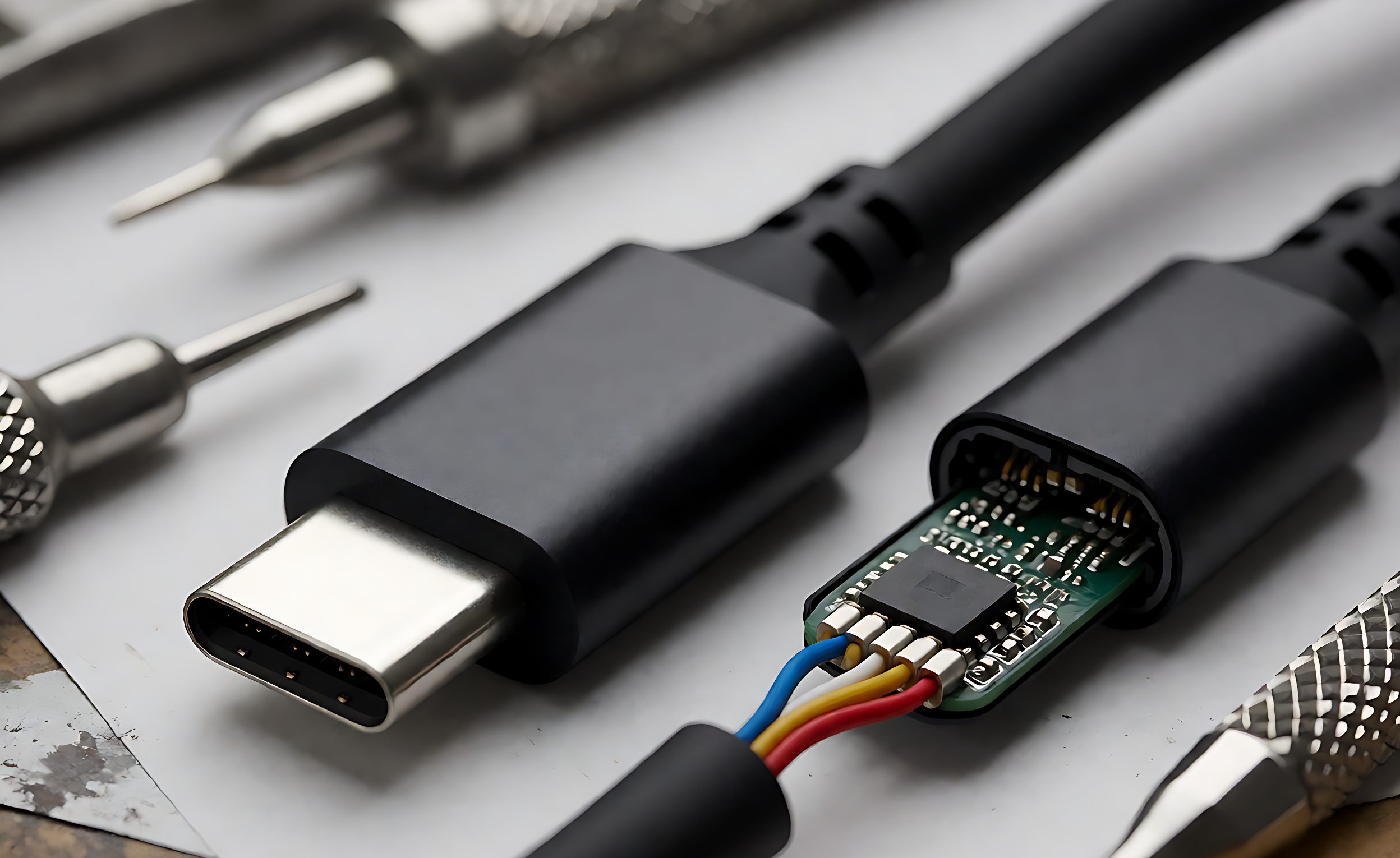
An assembly with a short, hard boot does the first job badly. The load path jumps from flexible jacket to rigid shell over a couple of millimetres, and the jacket tears exactly there. A longer, softer boot with a taper spreads the same load over a centimetre or more, which is why two cables that look similar in a photo behave completely differently after a year of use.
Material Choice: PVC, TPU, TPE and Silicone
Four materials cover most of the market, and the choice is driven by hardness, low-temperature behaviour, halogen content and cost, in roughly that order of engineering importance.
- PVC: inexpensive, easy to mold, good surface finish, but stiff at low temperature, contains halogen, and hardens with age. Fine for fixed installations, poor for a cable that flexes daily.
- TPU: the workhorse for flexible assemblies. Excellent abrasion resistance, good flex fatigue life, broad hardness range, and it bonds well to TPU jackets. Higher cost than PVC.
- TPE: softer feel, good grip, easier to achieve low hardness, but generally lower tear strength than TPU.
- Silicone: widest temperature range and the most flexible at cold, but expensive, low tear strength and difficult to bond, so it is usually a separate boot rather than an overmold.
Hardness is the number to write into the specification. Shore A around 60 to 75 is a common compromise for a boot that must flex but still resist tearing. Softer than 50 and the boot deforms under pull; harder than 85 and it behaves like the rigid shell it was meant to soften the transition to. Ask for hardness on the finished part, not on the pellet datasheet, because molding conditions shift it.
Jacket and boot materials should be chosen together. A TPU jacket with a PVC boot creates a hard-soft interface that concentrates stress at the bond line, which is a common and avoidable failure.
Geometry: The Part of the Specification Nobody Writes
Boot geometry is where most of the mechanical performance lives, and it is usually left to the toolmaker. Four dimensions matter.
- Boot length: the distance from connector face to the point where the boot meets the jacket. Too short concentrates stress; too long makes the assembly awkward in tight spaces. Twenty to thirty millimetres is typical for a hand-held cable.
- Taper: a gradual reduction in diameter from shell to cable. A step change is a stress riser regardless of material.
- Ribbing: circumferential ribs act as bellows, adding flexibility without thinning the wall. Two or three ribs near the cable exit substantially extend bend life.
- Exit angle: straight, 90 degree or 45 degree. Right-angle exits change the load direction entirely and must be evaluated with the minimum bend radius of the jacket in mind.
Specify these as nominal dimensions with tolerances, and require a first-article report that measures them on the molded part rather than on the drawing. A boot that is two millimetres short because the tool wore is a different product.
Process: Insert Molding, Low-Pressure Overmolding, Shell Assembly
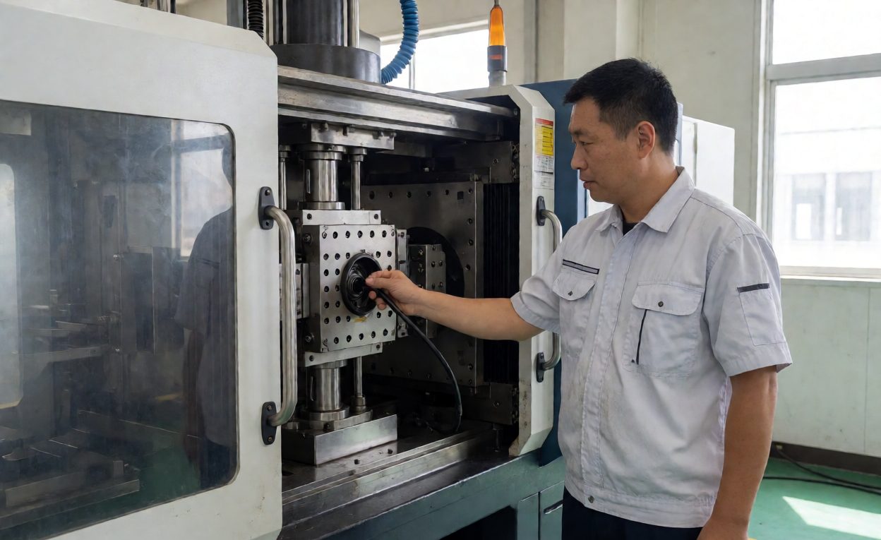
Insert overmolding places the terminated cable into a steel tool and injects material around it at high pressure. It produces the most durable result and the best seal, because the material encapsulates the joint. Tooling cost is real, typically a few thousand dollars per configuration, so it suits volume programmes.
Low-pressure overmolding uses a two-part polyurethane or hot melt at much lower pressure and temperature. Tooling is cheaper and lead time shorter, which suits low volume and prototypes. Bond strength and surface quality are lower, and the material is usually softer.
Shell assembly uses a two-piece plastic or metal shell snapped or ultrasonically welded around the joint, often with a separate strain relief boot. It is the cheapest route at low volume and the most common on commodity cables. It is also the least sealed, and the joint between shell halves is a reliable entry point for moisture.
The choice should follow the environment. A cable that lives on a desk can use shell assembly. A cable that gets dragged across a factory floor, coiled tightly and stepped on needs insert overmolding with a TPU boot, whatever the unit price difference says.
Tests That Produce Evidence
Datasheet cycle counts are marketing unless a report backs them. Four tests cover the mechanical case.
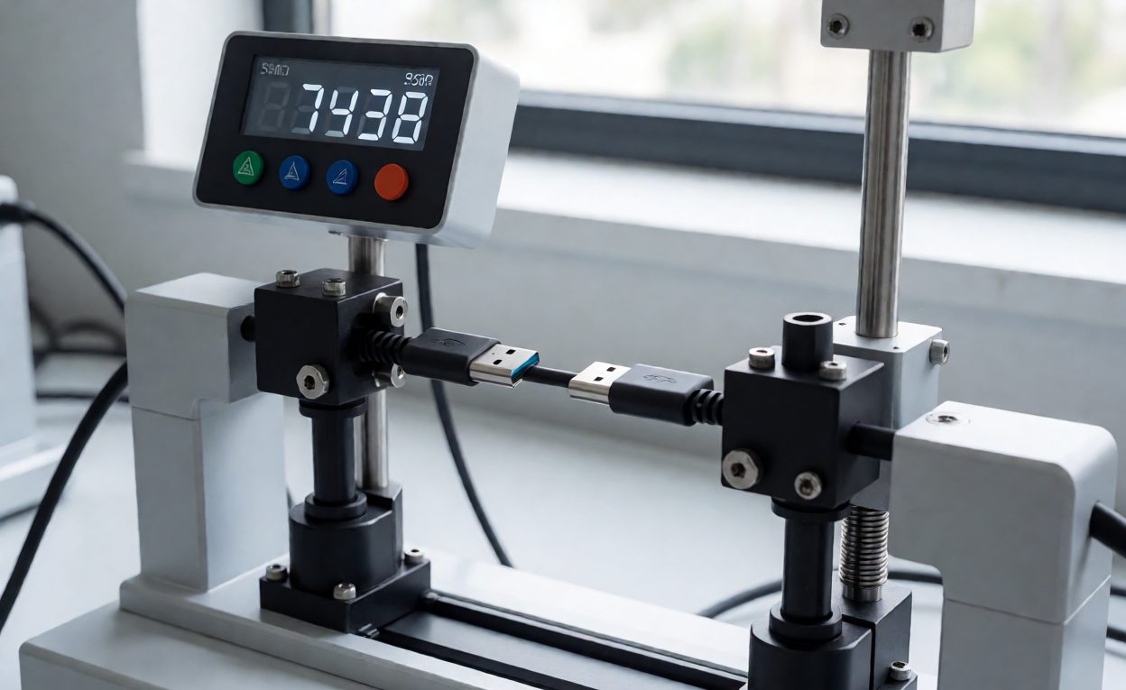
- Bend test: cycle the cable through a defined angle at a defined rate, typically plus or minus 60 to 90 degrees, and record the cycle count at first conductor failure. Ten thousand cycles is a reasonable entry bar; thirty thousand is a good flexible cable.
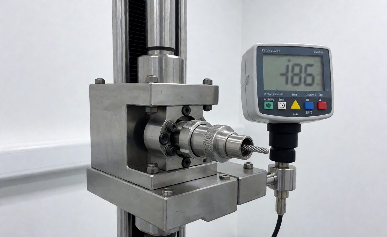
- Pull test: apply axial force to the connector and record the value at which the overmold separates or the jacket slips. Thirty to fifty newtons is a common target for a hand-held assembly.
- Torsion test: rotate the connector relative to the cable, which exposes bond failures that a pure bend test misses.
- Cold bend: condition at minus 20 or minus 30 Celsius and repeat a reduced bend sequence. PVC often fails here while TPU passes.
Connector durability is the other half of the story: insertion cycles wear the contacts and the latch, and a perfect overmold cannot compensate for a shell that loses retention after two thousand matings. The test report package should name the test standard, the sample size, the failure criterion and the actual result, not just a pass stamp.
Technical Background
Overmolding is a family of processes in which one material is molded over another, and the bond between them determines performance. Chemical compatibility matters more than adhesion promoters: a thermoplastic polyurethane boot bonds to a TPU jacket by partial melting at the interface, which is why same-family material pairs outperform mixed pairs.
The mechanical logic is straightforward once you see the boot as an elastomer spring. A soft, long spring distributes a given displacement over more material, lowering local strain. A short, hard spring concentrates the same displacement into a smaller volume and exceeds the material’s strain limit sooner. That is the entire reason ribbed, tapered boots outlast smooth, stubby ones, and it is a design choice rather than a material upgrade.
A Specification You Can Send to a Cable Factory
Write these lines into the drawing and the quotation will be comparable across suppliers.
- Overmold material and Shore A hardness on the finished part, with a tolerance of plus or minus 5.
- Boot length from connector face, taper profile, rib count and rib position.
- Exit angle and, for right-angle versions, the clearance envelope.
- Process: insert overmolding, low-pressure overmolding or shell assembly, stated explicitly.
- Pull force minimum, bend test angle, rate and pass cycle count.
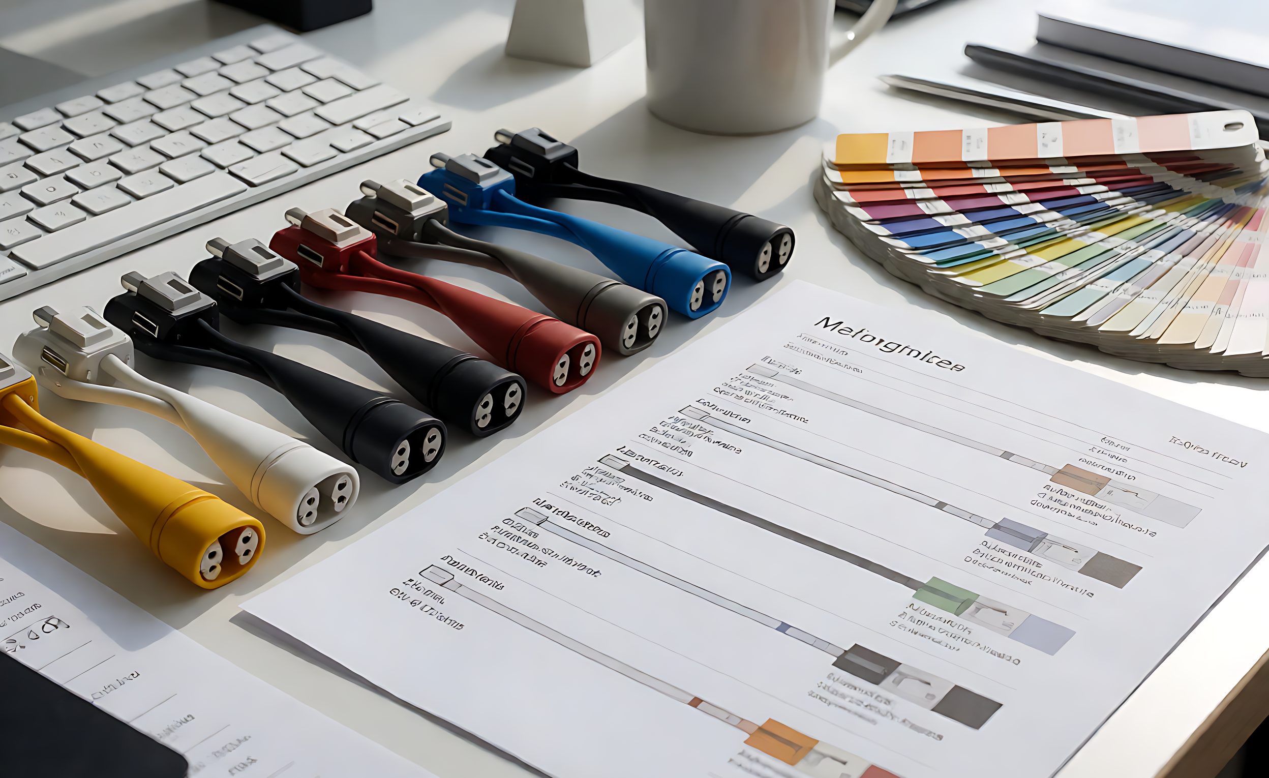
- Colour with a Pantone reference and a gloss level, plus a laser marking area if branding is required.
- Flammability rating if the cable enters an enclosure, and halogen status if the market requires it.
- First-article report requirements: dimensions, hardness, pull force and a bend test result on the actual lot.
What is the best material for a USB cable overmold?
TPU for anything that flexes in use: it combines abrasion resistance with good flex fatigue life and bonds well to TPU jackets. PVC is acceptable for fixed installations where cost dominates.
How long should a strain relief boot be?
Twenty to thirty millimetres is typical for a hand-held cable. The critical property is a gradual taper rather than a step, because a step change concentrates stress regardless of length.
What pull force should a cable assembly survive?
Thirty to fifty newtons axial is a common target for hand-held assemblies. Higher targets are achievable but usually require insert overmolding and a mechanical anchor inside the shell.
Is low-pressure overmolding good enough?
For low volume and light duty, yes, and the tooling cost is far lower. For repeated flexing, abrasion or moisture exposure, insert overmolding with TPU is the more durable route.
Why do PVC boots crack in cold weather?
PVC stiffens sharply as temperature drops and its strain at break falls. A cold bend test at minus 20 Celsius exposes this quickly, and TPU or TPE usually passes where PVC fails.
Can the overmold be a different colour from the cable?
Yes, and two-tone overmolds are common for branding. Specify both colours with references and confirm the bond between the two materials on a first article.
What does a bend test result actually mean?
It means the assembly survived a defined angle, rate and sample size without conductor failure. A cycle count without those parameters is not comparable between suppliers.