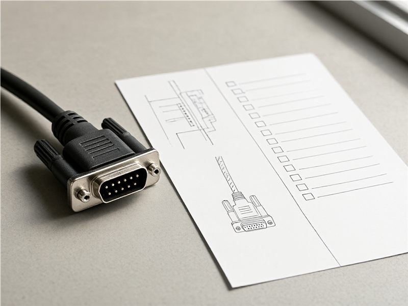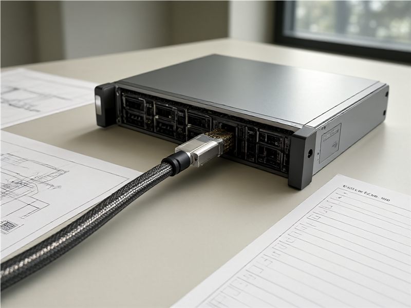

A mis-mate is one of the few cable harness defects that can destroy something expensive in under a second. Two connectors on the same panel differ only in pin count or keyway; an installer working in poor light or on a Friday afternoon pushes the wrong one home; power lands on a signal input and the board downstream becomes scrap. The cost is rarely the connector. It is the assembly, the module it was plugged into, and the diagnosis time afterwards.
Because the failure mode is human, the fix has to be physical. Warnings, training and a careful installer are all real protections and none of them are reliable at volume or across a fleet of field service engineers. Keying makes the wrong connection impossible rather than discouraged, and it is cheap to specify at the design stage and effectively impossible to add later.
What Keying Is For
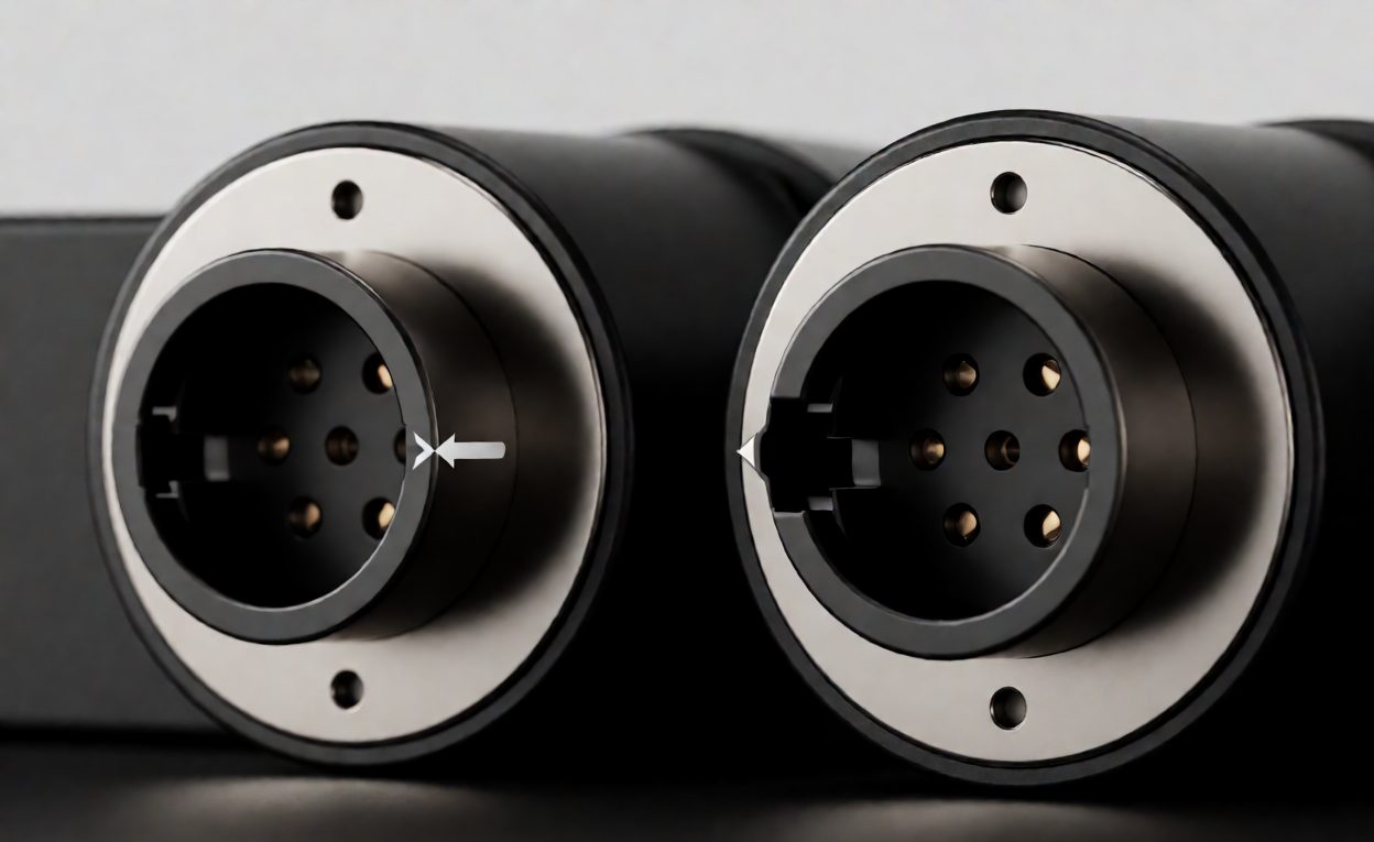
Keying is a geometric feature that allows a connector to mate only with its intended counterpart in its intended orientation. It solves two distinct problems that are often conflated. The first is mis-mating: connecting a plug to the wrong receptacle entirely, which is the expensive failure. The second is mis-orientation: connecting the right pair the wrong way round, which on a keyed circular connector is prevented by the same feature and on a symmetric connector is not prevented at all.
The design objective is that every connector on a panel should be distinguishable from every other connector it could plausibly be confused with, by a feature that does not depend on the installer reading anything. Where two connectors must be genuinely identical – a bank of the same sensor interface, for example – the requirement changes from distinction to labelling, and the remaining protection is that a swap does no harm.
Mechanical Keying Methods
- Keyway and key. A slot in the shell and a matching rib on the receptacle, with the angular position of the keyway encoding the variant. Circular industrial connectors use a catalogue of standard positions, which makes this the cheapest option when the standard positions are available.
- Asymmetric shell shape. A D-shape, a flat, or a sculpted body that only fits one way. Ubiquitous on D-sub and rectangular connectors, and the reason those families rarely suffer orientation errors.
- Pin-count and shell-size difference. Genuine protection when the two circuits differ in pin count, and worthless when they do not – which is the common case.
- Polarising posts and shrouds. Internal features that block insertion when the halves are rotated; used on board-level headers and on multi-row rectangular connectors.
- Non-standard keyway positions. Where the standard catalogue does not separate two variants, a custom keyway or a custom insert rotation does. It costs a little more and it is the only real answer on dense panels.
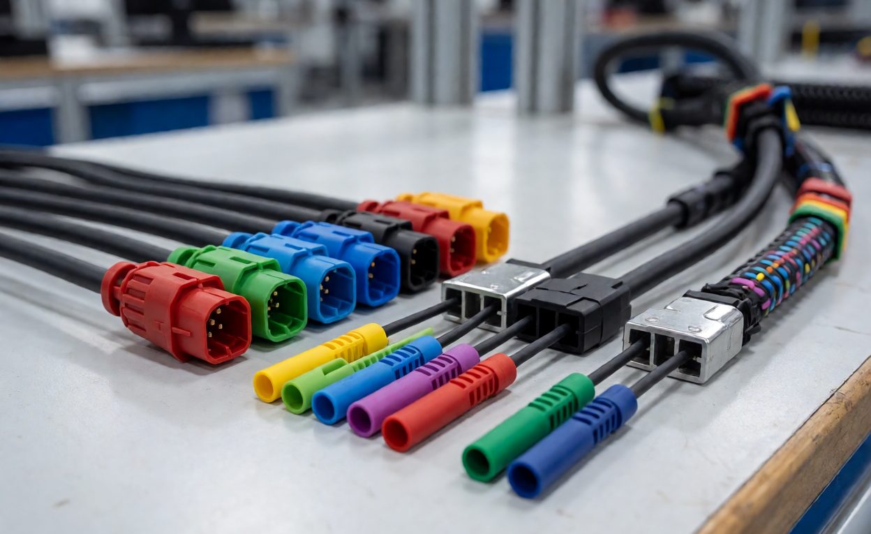
Thread and coupling differences also count as keying in practice. A bayonet connector will not mate with a screw-coupling receptacle, so specifying different coupling types across a panel is a legitimate way to separate populations of connectors – provided the difference is deliberate rather than accidental leftover from a previous design.
Colour Coding and Marking as a Secondary Defence
Colour is not keying. It does not stop a determined or hurried installer, it fades, it is inconsistent under different lighting, and it is invisible to a significant fraction of people. What it does extremely well is make the right answer obvious to someone who is trying, which is why it belongs in the design as a second layer rather than as the only one.
Used well, colour coding is systematic: the shell colour, the cable marker and the panel marking all use the same code, so an installer tracing a cable by its marker arrives at a receptacle of the same colour. Used badly, it is per-project and contradictory, and it teaches installers to ignore colour entirely. Marking at the panel – a printed legend next to each receptacle – is worth specifying at the same time, since it is the layer that survives when someone replaces a connector with an uncoloured spare.
Where Mis-Mating Still Happens
Patterns seen repeatedly in field returns and build-line defects:
- Spare and service connectors bought to the same part number because they looked the same on a photo, then fitted across two different circuits.
- Adapters and extension leads introduced during commissioning, which bypass the keying of the original pair entirely.
- Late design changes that add a second connector of the same family without revisiting keyway assignments.
- Reworked harnesses where a connector is replaced in the field and the replacement is a visually similar part with a different key.
- Symmetric connectors in blind-mate or hard-to-see locations, where orientation cannot be checked visually before pushing.
Technical Background
The design philosophy behind making the error physically impossible rather than merely detectable is poka-yoke, which is the frame most manufacturing engineering uses for this class of problem. The components being keyed are electrical connectors, whose families each define their own keying conventions, and the family where standardised keyway positions carry most of the burden in industrial harnesses is the circular connector, used precisely because its shell geometry supports multiple coded orientations.
Specifying Keying in a Harness Drawing
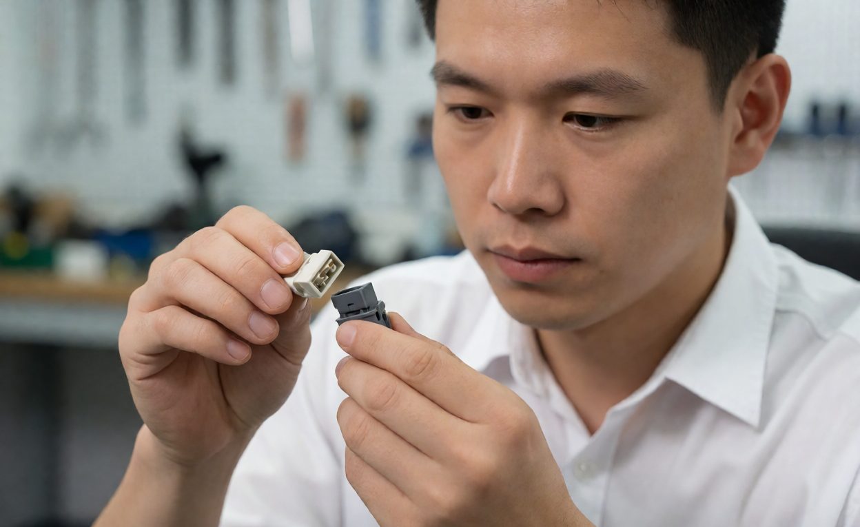
Four items make the requirement enforceable. First, a keying schedule: a table listing every connector position in the harness with its part number, keyway or coding, and mating counterpart, so a change to one line is visible against all the others. Second, the mechanical callout on each connector – keyway position, insert rotation, shell coding – stated rather than left to catalogue default. Third, the colour coding scheme, including what the panel-side marking must read. Fourth, a verification step: a first article checked for mating compatibility, including the deliberate attempt to mate each plug with the receptacles it must not fit.
That last test is the one that actually catches the problem, and it takes minutes. Attempting every wrong combination on the bench is far cheaper than discovering in the field that two connectors were interchangeable all along.
Keyway and coding decisions belong in the drawing package described in the drawing package buyers must specify, and connector selection for dense panels is discussed in high-density connectors for automation equipment. Harness build discipline is covered in professional harness manufacturing, connector family conventions in D-sub connector types in industrial applications, and mechanical verification in what a cable test report should contain.
Frequently Asked Questions
What is connector keying?
A geometric feature, usually a keyway and matching rib, that allows a connector to mate only with its intended counterpart in the correct orientation.
Is colour coding the same as keying?
No. Colour guides the installer but does not stop a wrong connection; keying makes the wrong connection physically impossible.
How do you separate two connectors of the same family?
Assign different standard keyway positions, or specify a non-standard keyway or insert rotation where the standard catalogue does not separate them.
Why do mis-mates still happen on keyed connectors?
Field rework with visually similar spares, adapters added at commissioning, and late design changes that never revisited the keyway schedule.
What is a keying schedule?
A table on the harness drawing listing each connector position with its part number, keyway or coding, and intended mating counterpart.
Should the harness be tested for mis-mating?
Yes. Deliberately attempt to mate each plug with the receptacles it must not fit; the check takes minutes and catches interchangeability.
Does a different pin count count as keying?
Only when the pin counts genuinely differ. Circuits with identical pin counts need a keyway, shell or coupling difference.