Prologue: The Ghost in the Machine
Every engineer has a story about the “ghost in the machine.” It is the story of a system that fails without reason, a bug that cannot be replicated, a gremlin that defies all logic. It is the story of a state-of-the-art server that inexplicably drops packets under load, a robotic arm that occasionally misses its mark, or a medical diagnostic device that throws a random error code, forcing a full system reboot. These ghosts haunt our designs, erode our confidence, and consume countless hours of our most valuable resource: engineering time. We hunt them in the software, we search for them on the circuit boards, and we model them in simulations. But we are often looking in the wrong place.
The truth is, these ghosts are not supernatural. They are the predictable and often inevitable consequence of a physical world that is actively hostile to the delicate dance of electrons that underpins our digital creations. They are the manifestation of vibration, of electromagnetic interference, of thermal stress, and of material fatigue. And their primary point of entry into our carefully designed systems, the conduit through which they wreak their havoc, is the most underestimated and undervalued component in the entire architecture: the physical connectivity. The cable, in all its forms, from the intricate Wire Harness to the simple data cable, is where the pristine world of digital logic collides with the messy, chaotic reality of the physical world.
This is not a story of blame; it is a story of empowerment. This is an engineer’s gambit—a strategic blueprint for confronting these forces head-on, for designing systems that are not just theoretically sound, but are practically indestructible. We will dissect the three fundamental forces that conspire to cause system failure—Mechanical Stress, Electrical Noise, and Thermal Fatigue. For each force, we will analyze its mechanisms and present a clear, actionable strategy for defeating it through the principles of high-quality, purpose-built connectivity. This is a guide to exorcising the ghost in the machine, one reliable connection at a time.
Part I: The Force of Mechanical Stress — The War Against Vibration and Fatigue
The first and most relentless enemy of reliability is mechanical stress. In the sanitized world of the design lab, our systems are static and stable. In the real world, they are in a constant state of motion. A data center rack hums with the vibration of a hundred fans. An industrial robot is a symphony of high-speed, repetitive movement. Even a device in a moving vehicle is subjected to a lifetime of shocks and tremors. This constant, kinetic energy is a potent force for failure, and it attacks our systems at their most vulnerable points: the connections.
The Mechanism of Failure: Micro-Movements and Material Fatigue
Mechanical stress causes two primary modes of failure in a Cable Assembly:
- Connector Fretting and Disconnection: This is the most common failure mode. A standard friction-fit connector relies on simple spring tension to maintain contact. Under constant vibration, the connector experiences “fretting,” a micro-motion that can wear down the contact surfaces and, more critically, can allow the connector to slowly “walk” its way out of the port. This leads to the maddening intermittent failures that are the hallmark of the “ghost in the machine.”
- Conductor and Shield Fatigue: In applications with repeated bending and flexing, like a robotic arm or the hinge of a laptop, the copper conductors and the braided shield are subjected to immense physical strain. Like a paperclip being bent back and forth, the metal will eventually fatigue and break, leading to a complete open circuit and a hard failure.
The Engineer’s Gambit: Designing for Mechanical Resilience
Conquering the force of mechanical stress is not a matter of hope; it is a matter of deliberate design choices. The strategy is to build a physical layer that is immune to these forces.
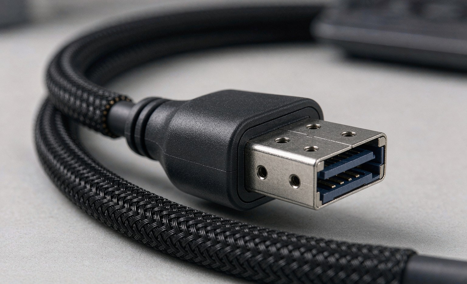
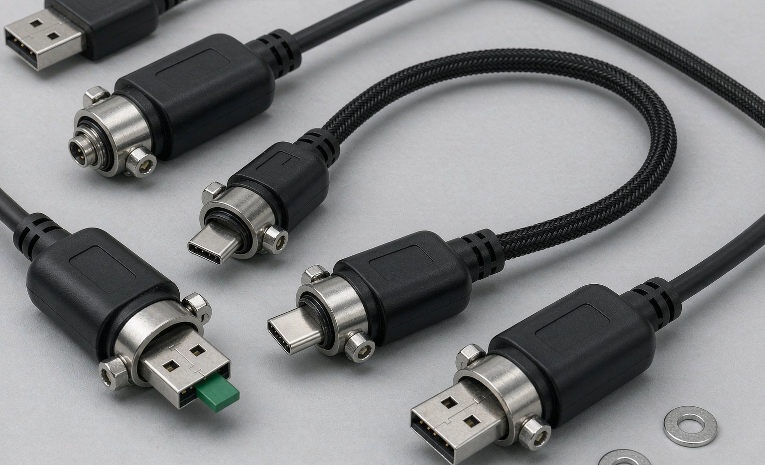
- The Mandate for Mechanical Locking: For any system that will experience vibration—which is virtually any system outside of a home office—a mechanical locking connector is not an optional upgrade; it is a fundamental design requirement. The robust, screw-down mechanism of a USB Cable locking connector or the secure latch on a MINI SAS or SlimSAS Cable connector transforms the connection from a temporary friction fit into a semi-permanent, vibration-proof interface. This single choice is the most powerful move an engineer can make to eliminate intermittent connection failures.
- The Science of High-Flex-Life Design: For dynamic applications, the solution is to specify a cable that is purpose-built for high-flex-life. This is a specialized engineering discipline that involves using high-strand-count, ultra-fine copper conductors that are more flexible than solid wires. It involves using advanced insulation and jacket materials, like TPE or a specialized PUR, that are designed to reduce internal friction and move smoothly. And it involves a robust strain relief that is co-molded to the connector to prevent stress from being concentrated at the delicate termination points. A properly engineered robotic-grade Industrial Cable is designed and tested to withstand millions of flex cycles without failure.
- The Art of the Strain-Managed Wire Harness: In a complex system, the routing and management of the cables is as important as the cables themselves. A well-designed Wire Harness is an exercise in strain management. It is built to a precise length to eliminate unnecessary slack. It uses service loops to allow for movement without putting stress on the connectors. It is secured to the chassis at strategic points to isolate it from vibration. This holistic approach to the assembly’s design is a critical part of the defense against mechanical failure.
Part II: The Force of Electrical Noise — The Battle for a Clean Signal
The second great enemy of reliability is electrical noise, or electromagnetic interference (EMI). Our digital systems communicate using delicate, high-frequency electrical signals. The world, however, is a storm of stray electrical energy from power lines, motors, radio transmitters, and even the other components within the system itself. This EMI can overwhelm the data signal, corrupting it and causing errors, slow performance, or a complete loss of communication. The battle for reliability is, in many ways, a battle to maintain a clean signal in a noisy world.
The Mechanism of Failure: Signal Corruption and Crosstalk
Electrical noise attacks a signal in two primary ways:
- External Interference (EMI/RFI): This is noise that originates from outside the cable. In a factory, the powerful magnetic fields from a motor can induce a current in a nearby, unshielded data cable, completely scrambling the ones and zeros. In a data center, a high-power server power supply can radiate noise that interferes with adjacent cables.
- Internal Interference (Crosstalk): This is noise that originates from within the cable itself. In a multi-pair cable, the signal traveling down one pair can “bleed” over and interfere with the signal on an adjacent pair. This problem becomes exponentially worse as data speeds increase, and it is a primary limiting factor in the performance of high-density connectors.
The Engineer’s Gambit: Architecting a Fortress of Shielding
The strategy for defeating electrical noise is to build a fortress around the signal. This is the science of shielding, a multi-layered defense system that is the defining characteristic of a high-quality data cable.
-
- The Principle of the Faraday Cage: A shield works by creating a conductive enclosure around the signal wires. This enclosure, known as a Faraday cage, intercepts the external EMI and safely conducts it to ground, preventing it from ever reaching the sensitive conductors within.
–The Synergy of Multi-Layer Shielding: A truly robust shield is not a single layer. It is a synergistic combination of different types of shielding, each designed to combat a different type of noise. A high-performance Industrial Cable or server data cable will typically feature:
-
- Individual Pair Foils: Each twisted pair of conductors is wrapped in its own aluminum foil shield. This is the primary defense against internal crosstalk, isolating each pair from its neighbors.
- An Overall Foil Shield: The entire bundle of pairs is then wrapped in another, overall foil shield. This provides the first layer of defense against high-frequency external EMI.
- A Tinned Copper Braid: The final layer is a woven braid of copper wires. This braid is extremely effective at blocking low-frequency EMI (the kind generated by motors) and also adds significant physical strength and abrasion resistance to the cable.
- The Importance of a 360-Degree Ground Connection: A shield is only effective if it is properly grounded at the connector. A high-quality connector will have a metal backshell that makes a full, 360-degree connection to the cable’s braid and drain wire. This ensures that the captured noise has a low-impedance path to ground. A cheap, plastic connector or a poorly terminated shield renders the entire defense system useless.
Part III: The Force of Thermal Fatigue — The Silent War of Expansion and Contraction
The third, and perhaps most insidious, force of failure is thermal stress. Every electronic component generates heat, and every system is subject to changes in ambient temperature. These temperature fluctuations cause the materials within a cable assembly—the copper, the plastic, the solder—to expand and contract. While these movements are microscopic, they happen thousands of times over the life of the system. This constant cycle of expansion and contraction creates immense stress on the assembly’s weakest points, leading to a slow, silent process of fatigue and eventual failure.
The Mechanism of Failure: Solder Joint Fatigue and Material Degradation
Thermal stress manifests in two main failure modes:
- Solder Joint Cracking: The point where a pin is soldered to a circuit board or a wire is soldered to a connector pin is a junction of dissimilar materials, each with a different coefficient of thermal expansion. As the system heats up and cools down, these materials expand and contract at different rates, putting immense stress on the brittle solder joint. Over thousands of cycles, this can cause microscopic cracks to form, leading to a high-resistance or completely open connection.
- Material Degradation: The plastic materials used for insulation and jacketing can also be broken down by heat. Over time, high temperatures can cause these materials to become brittle and crack, compromising their insulating properties and their physical protection of the conductors.
The Engineer’s Gambit: Designing for Thermal Resilience
Conquering thermal fatigue requires a deep knowledge of material science and a commitment to manufacturing processes that are designed for long-term stability.
-
- The Choice of High-Temperature Materials: For any system that will operate at elevated temperatures, such as an automotive engine compartment or a densely packed server, the cable must be constructed with high-temperature materials. This includes insulation materials like FEP (Fluorinated Ethylene Propylene) and jacket materials that have a high continuous operating temperature rating (e.g., 105°C or 125°C).
- The Art of a Resilient Solder Joint: The reliability of a solder joint is a direct function of the quality of the manufacturing process. A world-class manufacturer uses a precisely controlled reflow soldering process with a specific temperature profile to ensure a strong, uniform intermetallic bond. They also use advanced solder alloys that are specifically designed to be more resistant to thermal fatigue. After soldering, every assembly should be subjected to an inspection process (often automated) to ensure the quality of every joint.
–The Power of Mechanical Crimping: In many high-reliability applications, a mechanical crimp is preferred over a solder joint. A well-executed, gas-tight crimp creates a robust mechanical and electrical bond that is far more resistant to the forces of vibration and thermal cycling than a standard solder joint. The quality of this crimp is a direct result of using high-precision, manufacturer-certified tooling.
The Synthesis: A Partnership in Quality as the Ultimate Gambit
The engineer’s gambit against the forces of failure is a multi-front war. It requires a holistic strategy that addresses mechanical, electrical, and thermal stresses with equal rigor. It is a strategy that is impossible to execute alone. It requires a deep and collaborative partnership with a manufacturer that not only understands these forces but has built their entire operation around the principle of conquering them.
This is the fundamental value proposition of a true quality-focused manufacturer like Longkai Electronics. Our role is not merely to be a supplier of components, but to be a strategic partner in our clients’ war against failure.
-
- Our Expertise is Your Asset: With a legacy of engineering excellence stretching back to 2012, we have spent over a decade on the frontlines of this battle. We bring this accumulated expertise in material science, high-frequency engineering, and advanced assembly techniques to every project.
–Our Quality Systems are Your Shield: Our commitment to reliability is not a claim; it is a system. Our ISO 9001 certified quality management system, our rigorous in-process controls, and our 100% final testing protocol are the shield that protects your system from the forces of failure.
–Our Collaboration is Your Advantage: We work with our clients as an extension of their engineering teams. Through our robust OEM/ODM process, we help design and build custom-tailored Cable Assembly and Wire Harness solutions that are not just compliant, but are fundamentally resilient, architected from the ground up to win the war against the ghost in the machine.
Conclusion: From Haunted Systems to Hardened Designs
The ghosts that haunt our systems are real, but they are not supernatural. They are the predictable outcomes of physical forces that we can understand, anticipate, and defeat. The engineer’s gambit is to refuse to be a victim of these forces and to instead become a master of them. It is a strategic decision to move beyond the short-sighted compromises of low-cost components and to embrace a design philosophy where reliability is not an afterthought, but is the primary and non-negotiable goal.
By architecting for resilience—by choosing the right materials, demanding precision assembly, and forging a partnership with a manufacturer who shares this commitment—we can transform our designs from haunted systems into hardened, reliable workhorses. We can exorcise the ghosts, not with magic, but with the potent and enduring power of engineering excellence.