Quick answer: An Oculink cable specification should identify the exact interface references at both ends, connector orientation, intended system, route, length and verification needed by the equipment owner. Buyers should confirm compatibility with the host and device documentation, review a representative sample and keep results tied to the cable revision. A connector family name alone does not define every lane, wiring or mechanical detail required by a system.
1. Confirm the host and device interface references
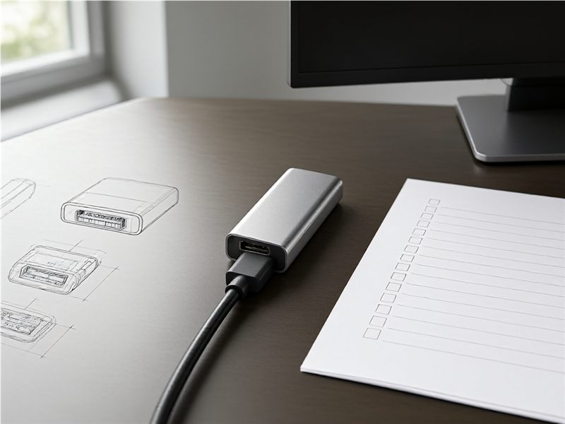
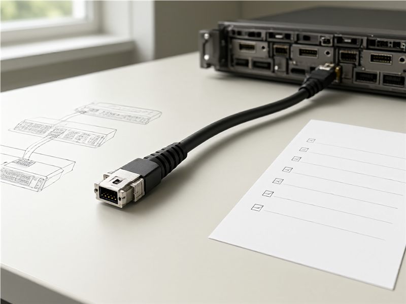
List the equipment at both cable ends and cite the interface drawing or approved system reference used for each. Record connector designation, gender, keying and viewing direction. If the assembly connects different interface variants, write the exact end-to-end arrangement instead of calling both ends “Oculink.” Ask the system owner to confirm the expected signal and lane configuration. This avoids treating an interface label as a complete cable definition and gives the supplier a precise basis for the quotation and sample build.
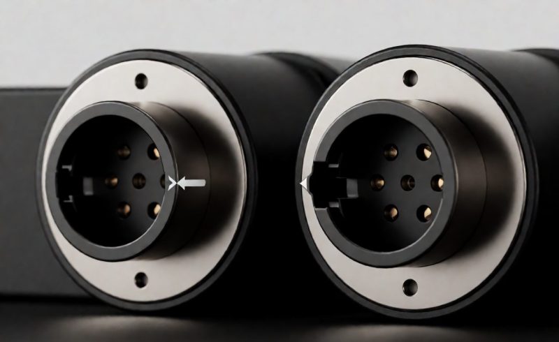
2. Specify connector orientation and access
Show how each connector faces after installation, including latch access, board clearance and cable exit direction. Mark the top or datum side on the drawing and label end A and end B consistently. If one connector is near a panel or card edge, include a view of the surrounding space. A cable can have the correct connector family yet be difficult to install if its orientation conflicts with the chassis. A simple fixture or photo with annotated direction can make the intended build easier to review.
3. Record lane and wiring expectations
Provide the system owner’s approved lane, pin or wiring information for the cable assembly and identify which record controls the build. Ask the supplier to state any assumptions or proposed mappings. A second reviewer should compare the cable drawing with the host and device documentation before release. Do not copy a lane or pin map from a different system just because the connector looks similar. Tying the wiring definition to the equipment revision helps prevent a mechanically correct assembly from being accepted with an unverified electrical arrangement.
4. Map the cable route, length and bend space
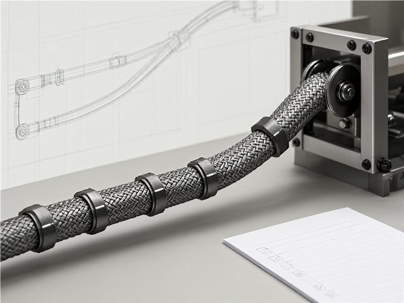
Show the intended route from the host connector to the device, including bends, entry points, retention, service loop and obstructions. Define length endpoints and tolerance. Include whether the cable is static or moves as part of a service action. If the installation passes behind a bracket or through a compact enclosure, check clearance with the actual dimensions. A representative route helps the supplier and buyer identify whether a straight or angled connector is required and where strain relief should be reviewed.
5. Identify the cable construction and environment
State the construction, shielding, jacket, labeling and operating conditions required by the product specification. Have the responsible engineer confirm any system-level performance requirement and the document that governs it. Avoid assumptions based solely on connector shape or a supplier category page. Ask the supplier to list substitutions in writing and connect them to a sample or test record. This helps procurement compare proposals without losing the technical details that determine whether a cable is suitable for the intended host and device.
6. Fit the sample on the real interface
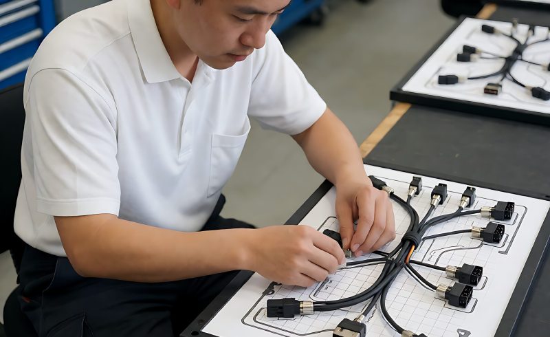
Use a sample with the specified end configuration and route it through the intended equipment or a representative fixture. Check insertion, retention, latch access, cable exit, bend clearance and service removal. Record the host and device model or fixture used. Keep fit observations separate from electrical validation. If the sample requires an installation workaround, document it and decide whether the drawing or cable configuration should change before production. A recorded fit trial is more reliable than a photograph of an unattached cable.
7. Define verification and production records
Ask the system owner to identify applicable electrical or signal verification and the method the supplier should report. Tie each result to the cable assembly code and revision. Include lot or build identifier, test date and any deviation. Do not treat a connector inspection or continuity check as proof of system-level behavior unless the approved test plan says so. A clear evidence package gives engineering a traceable record for evaluating the sample and receiving later production lots.
8. Control revisions and service replacements
Store the interface references, pin or lane record, route, sample-fit result, construction and test evidence together. Require notice before the supplier changes connector source, wiring, jacket, length or production process. Use the same assembly code on the drawing, label and purchase order. When the host board, device or enclosure changes, recheck the cable rather than assuming the previous sample still fits. This creates a useful history for service teams and supports a more reliable repeat order.
For buyers comparing available product and supplier options, see Longkai Oculink cable assemblies.
Questions buyers often ask
Is “Oculink cable” enough detail for a purchase order?
No. Identify both interfaces, connector orientation, system reference, lane or wiring expectations, route and length.
What should a cable fit trial check?
Review mating, retention, latch access, route, bend space and service access on the intended equipment or fixture.
Who should approve lane or pin mapping?
The equipment or system owner should verify the mapping against current host and device documentation.
When should the cable be reviewed again?
Reopen review when the interface, wiring, route, length, source or equipment revision changes.