Quick answer: An M12 cable assembly brief should identify both connector ends, coding, pin count, pinout, cable length, jacket, route and the equipment revision it serves. Buyers should confirm the interface with the system owner, define the checks required for a sample and record installation assumptions. The M12 name by itself does not specify every connector, wiring or environmental detail needed for a production order.
1. Identify the connected equipment and job
Name the equipment at each end of the assembly and describe whether the cable carries power, data, signals or a defined combination. Include the product or system revision and the installation location. A machine sensor connection, control cabinet link and fieldbus drop can require different connector and cable details even when each uses an M12 style interface. Provide the supplier with the actual use case and the buyer’s intended service conditions. This gives the cable brief a practical boundary and helps the system owner review whether the proposed assembly matches the equipment, rather than relying on a connector family name alone.
2. Specify the connector coding and pin count
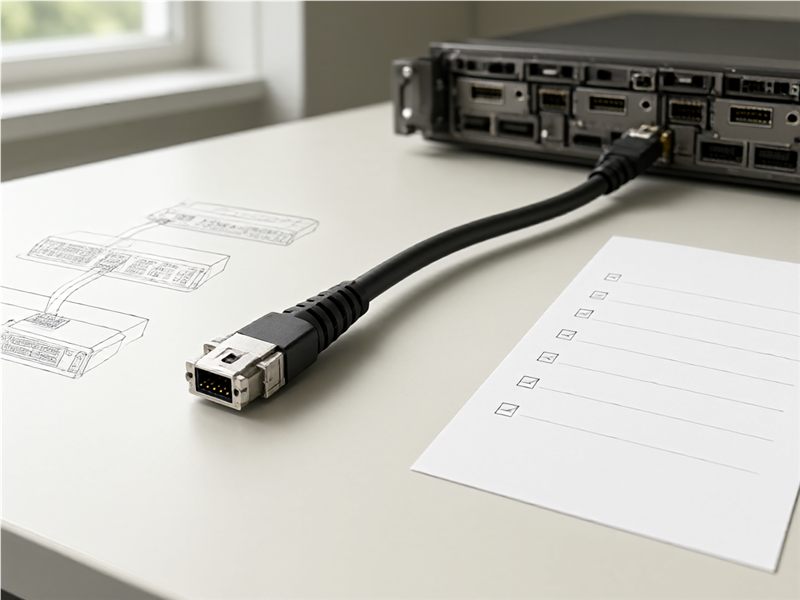
Record the connector gender, coding, number of contacts, keying, straight or angled body and viewing direction at each end. Identify end A and end B on a drawing and label the mating face so the pin numbering is unambiguous. If the cable has different connector types at either end, describe both separately. Have the equipment owner confirm the code against the device documentation. These details matter for both fit and signal routing; a connector photograph may show the shell but not the internal pin arrangement or the orientation expected by the machine.

3. Attach the approved pinout and wire map
Provide the pin-to-pin map, conductor identification and any shield or drain termination requirement that applies to the assembly. State the reference direction used to number each connector and the source document revision. If the order includes straight-through and crossed versions, assign different part numbers and keep their drawings separate. Ask the supplier to return a marked-up drawing or continuity record for the sample. The system owner should approve the electrical mapping before the cable is released. Clear maps prevent a production lot from being assembled to a different interpretation of a pin number or connector face.
4. Define length, jacket and route constraints
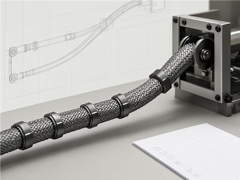
Specify cable length with a measurement reference, such as connector interface to connector interface or an agreed breakout point. Show the intended route, bend locations, moving sections, tie points and service loop. State the jacket, color and construction requirements based on the actual application, and assign the responsible engineer to confirm any temperature, fluid, cleaning or motion assumptions. Do not use a vague “industrial grade” phrase in place of a defined environment. A route drawing lets the supplier check that the assembly can reach the connection points without placing unnecessary strain on the cable.
5. Confirm shielding, grounding and interface ownership
Describe any shielding or grounding expectation and identify which equipment drawing or system owner controls that decision. Keep the connector-shell termination, cable shield and machine ground reference explicit where the application requires them. The supplier can quote the specified construction, but should not infer the machine’s electrical design from a picture. If the cable routes near noise sources or through a moving assembly, tell the responsible engineering team and document the review. This keeps the technical decision with the person who owns the equipment interface and gives the buyer a clear record for future service replacements.
6. Agree on sample checks and evidence
List the checks required for a representative sample: connector identification, orientation, fit with the mating device or approved gauge, length, pinout, continuity, jacket marking or other requirements set by the buyer. Name the person who performs each check and the record that should be returned. Keep each result tied to the assembly code and drawing revision. Do not treat a continuity result as proof of every environmental or performance property. If the buyer requires additional testing, state the method and acceptance criteria before the sample is built so supplier and buyer use the same basis.
7. Prepare markings, labels and spare-part identity
Specify whether the cable needs a label at one end, both ends or at the pack level. Include the assembly part number, revision, end designation and any required lot or trace reference. Ensure markings remain readable after installation and do not obscure the connector coding or release feature. If distributors or maintenance teams order replacement cables, give them a stable item identifier and a way to distinguish length or pinout variants. These details make the approved assembly easier to receive, install and reorder without relying on a photo or a manually remembered configuration.
8. Tie the release and change notice to the order
Store the connector drawings, pinout, length, jacket, route, sample results, label reference and approval date in one release record. Use the same assembly code in the purchase order and supplier documents. Ask the manufacturer to notify the buyer before changing connector source, contact mapping, cable construction, jacket, length or assembly process. When the connected machine changes, recheck the interface rather than assuming the earlier cable remains suitable. A controlled record helps engineering answer service questions and allows procurement to compare a repeat lot with the actual version that was approved.
For buyers comparing available product and supplier options, see Longkai industrial cable assemblies.
Questions buyers often ask
Is “M12 cable assembly” enough information for an RFQ?
No. Add connector coding, gender, pin count, pinout, length, route and application details.
Who should confirm an M12 pinout?
The equipment or system owner should verify it against the current device and machine documentation.
What should a sample check include?
Use the buyer’s defined fit, orientation, length, pin mapping and test record requirements.
When should the cable be reviewed again?
Reopen review when connector details, pinout, equipment revision, route or operating assumptions change.