Quick answer: Select an industrial cable by documenting where it routes, whether it moves, what environment it faces, which electrical and mechanical interfaces it needs and how the finished assembly will be verified. A connector list alone is not enough to establish that a cable suits the installation or remains serviceable.
1. Map the cable route from end to end
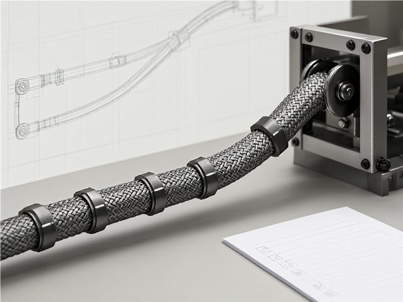
Draw the path between connection points and identify fixed and moving sections, bend locations, clamp points, pass-throughs and service access. Include the installed equipment orientation and any nearby power or signal runs that affect routing. Mark the route length and how it was measured. If the cable must pass through a chain, conduit or panel opening, give the relevant dimensions and restrictions. A routing drawing helps the supplier understand the actual assembly instead of inferring it from a connector list. Ask the installer or machine designer to verify the drawing against the equipment layout before the cable is approved.
2. Define electrical signals and interfaces
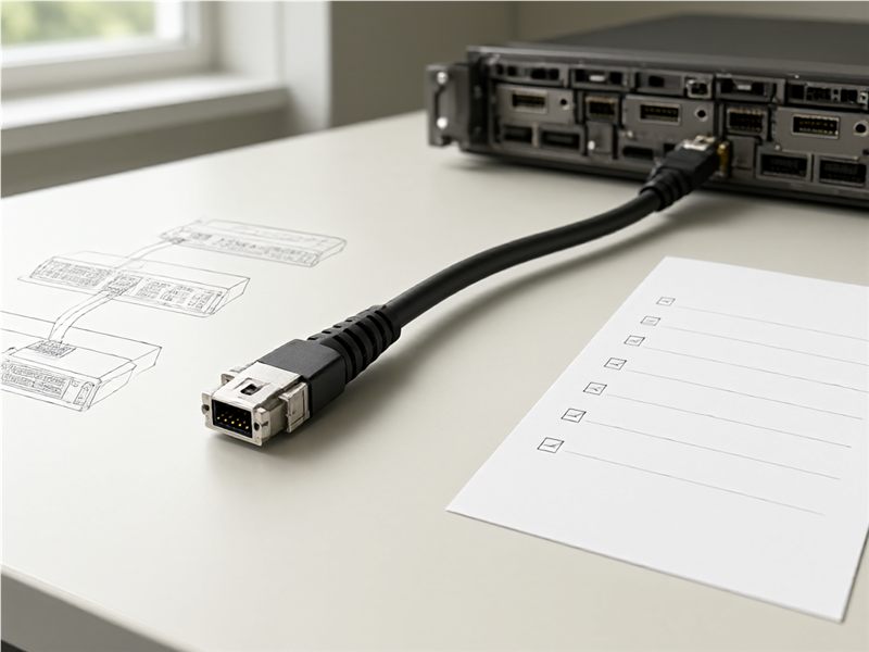
List the required signal or power function, connector series, pinout, mating orientation, length and interface at each end. Attach the schematic, connector drawings and any equipment-maker instructions. Identify which conductors or contacts are used and whether any pins must remain unconnected. If the cable is part of a controlled system, reference the interface revision and owner. Ask the supplier to confirm the proposed mapping and show how it will be verified. Do not assume two connectors with the same general family name share the same pinout or application. A connection table can prevent a mechanically correct cable from being electrically miswired.
3. Describe motion and mechanical stress
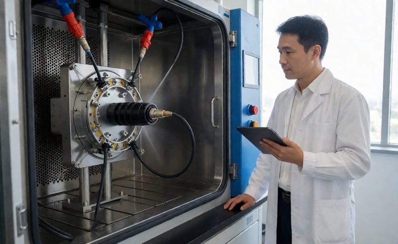
State whether the assembly is static, flexed occasionally, moved continuously or subject to torsion, vibration or repeated handling. Identify the movement range, cycle context and route geometry that the cable must accommodate. Ask the supplier what construction and test evidence is relevant to the proposed use. Avoid using a generic “flexible” label as proof of a particular service life. If the cable moves with a robot, carriage or machine door, share the equipment motion and fix points. A representative sample should be evaluated in the intended route because a cable can behave differently when clamped, bent or bundled with other lines.
4. Review the environment and protective needs
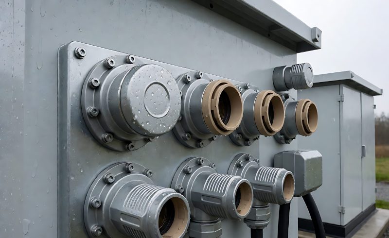
Describe exposure to abrasion, oil, cleaning agents, moisture, temperature, dust or electromagnetic interference where relevant. State which conditions are confirmed and which require a site review. Identify whether the cable runs indoors, outdoors or through a protected enclosure and whether it will contact other materials. Ask the supplier to identify the jacket and shielding options that match the documented conditions and what evidence supports the selection. Do not infer a rating or environmental capability from color or appearance. If a specification requires a particular rating, confirm the exact test or product documentation and its applicability to the assembled cable.
5. Confirm connector, shielding and grounding details
Specify connector keying, shell, backshell, strain relief, shield termination and grounding approach according to the system design. Show which end connects to which device and how the shield is intended to be terminated. If an equipment manual prescribes routing or separation, include that instruction. Ask the supplier to identify any assumptions about the mating connector or enclosure. Confirm that the selected connector can be installed and serviced in the actual space. Keep the connector code and revision in the bill of materials so replacement assemblies do not introduce an unnoticed interface change.
6. Plan installation, clamping and service access
Mark where the cable is supported, how much slack is available and which areas need access for inspection or replacement. Identify clamps, glands, ties or protective sleeves that are part of the assembly or supplied separately. Check that installation will not place an unintended load on the connector or obstruct maintenance. Ask the machine designer to review bend and clearance assumptions. If the cable will be routed through an existing assembly, provide photographs with the route marked and measurements where possible. A serviceable design should allow the cable to be identified and changed without damaging adjacent equipment or relying on undocumented routing knowledge.
7. Set the verification and documentation scope
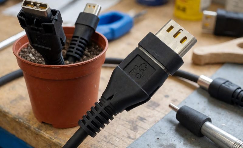
List continuity, pin mapping, functional, insulation or mechanical checks that apply to the assembly and have the responsible engineering owner confirm the appropriate method. State sample quantity, acceptance criteria, report format and the revision identification required on each record. Ask who performs each test and what evidence accompanies the production shipment. If the customer requires a certain certificate or industry standard, identify it specifically and confirm scope with the compliance adviser. Do not add a standard simply because it appears in another cable specification. Tie the test record to the cable part number, connector configuration and production revision.
8. Control replacements and design changes
Record cable length, connectors, pinout, construction, shielding, jacket, markings and routing reference under a stable part number. Define how an equivalent or alternate component is reviewed and who approves it. When equipment or route changes, assess whether the existing cable still meets bend, environment and interface requirements. Maintain a list of installed revisions so service teams can request the correct replacement. If cables are cut or assembled on site, state who is responsible for inspection and how the finished assembly is marked. These controls keep a substitute from being accepted based only on connector fit.
9. Send a complete industrial cable request
Include the route drawing, motion description, environment, interface and pinout, connector details, shielding and grounding approach, length, test matrix and replacement expectations. Ask the supplier to state assumptions and evidence for any proposed construction. Review Longkai industrial cable assemblies and provide the equipment context so the cable can be matched to the installation rather than selected from a broad category alone.
For buyers comparing available product and supplier options, see Longkai industrial cable assemblies.
Questions buyers often ask
What information matters most for a moving industrial cable?
Provide the route, movement type, bend locations, support points, environment and relevant cycle or service context, then request evidence for the proposed construction.
Can I select a cable by connector type only?
No. The connector does not specify pinout, electrical function, routing, motion, environment or shielding. Include those requirements in the brief.
Who should define shielding and grounding?
The equipment or electrical design owner should specify the interface and grounding approach, with supplier input on the cable construction.
How do I make a replacement cable easier to order?
Keep a stable part number with the route, connectors, pinout, construction, length, revision and installation record.