Impedance is the most cited and least specified number on a high-speed cable enquiry. Buyers ask for ninety or one hundred ohms, suppliers confirm it, and the assemblies arrive and work or do not. When they do not, the argument usually turns on what was measured, at what frequency, over what length, and with what reference. Those four details are the specification, and they are rarely written down.
The underlying idea is worth stating plainly because it determines everything else: impedance is not a setting on a machine and not a property that can be adjusted after manufacture. It falls out of geometry and materials. Once the conductor diameter, the dielectric and the spacing to the shield are fixed, the impedance is fixed, and testing only reveals what the process actually produced.
Why Impedance Is a Property of Geometry
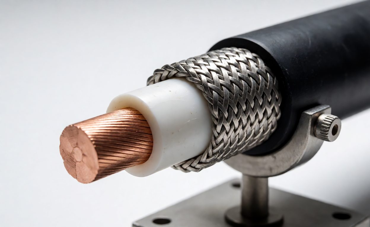
The characteristic impedance of a transmission line is set mainly by four things: the conductor diameter, the dielectric constant of the insulation, the distance between conductor and return path, and the geometry of that return path. A coax with a larger center conductor has lower impedance. A dielectric with a lower dielectric constant raises it. Moving the shield closer lowers it. Foaming the dielectric to reduce its effective dielectric constant is one of the main levers manufacturers use to make a thin cable hit a target impedance.
That relationship explains two things buyers experience. First, why impedance-controlled cable costs more: the geometry has to be held during extrusion, and the tolerance on conductor diameter, concentricity and dielectric thickness is tighter than on ordinary wire. Second, why a flexible assembly drifts: any change in geometry along the length changes the impedance locally, and the places where geometry changes are exactly the places where problems appear.
- The termination. Where the controlled geometry ends and a connector begins, the cross-section changes abruptly and impedance steps.
- The solder joints. A joint is a short length of uncontrolled geometry, and at multi-gigabit rates a short length is not short.
- The breakout. Where pairs separate from a shielded bundle, the return path moves and the impedance follows it.
- Bends and dressing. Tight bending compresses the dielectric and shifts the geometry, which shows up as a localized impedance change.
What Signal Integrity Testing Actually Measures
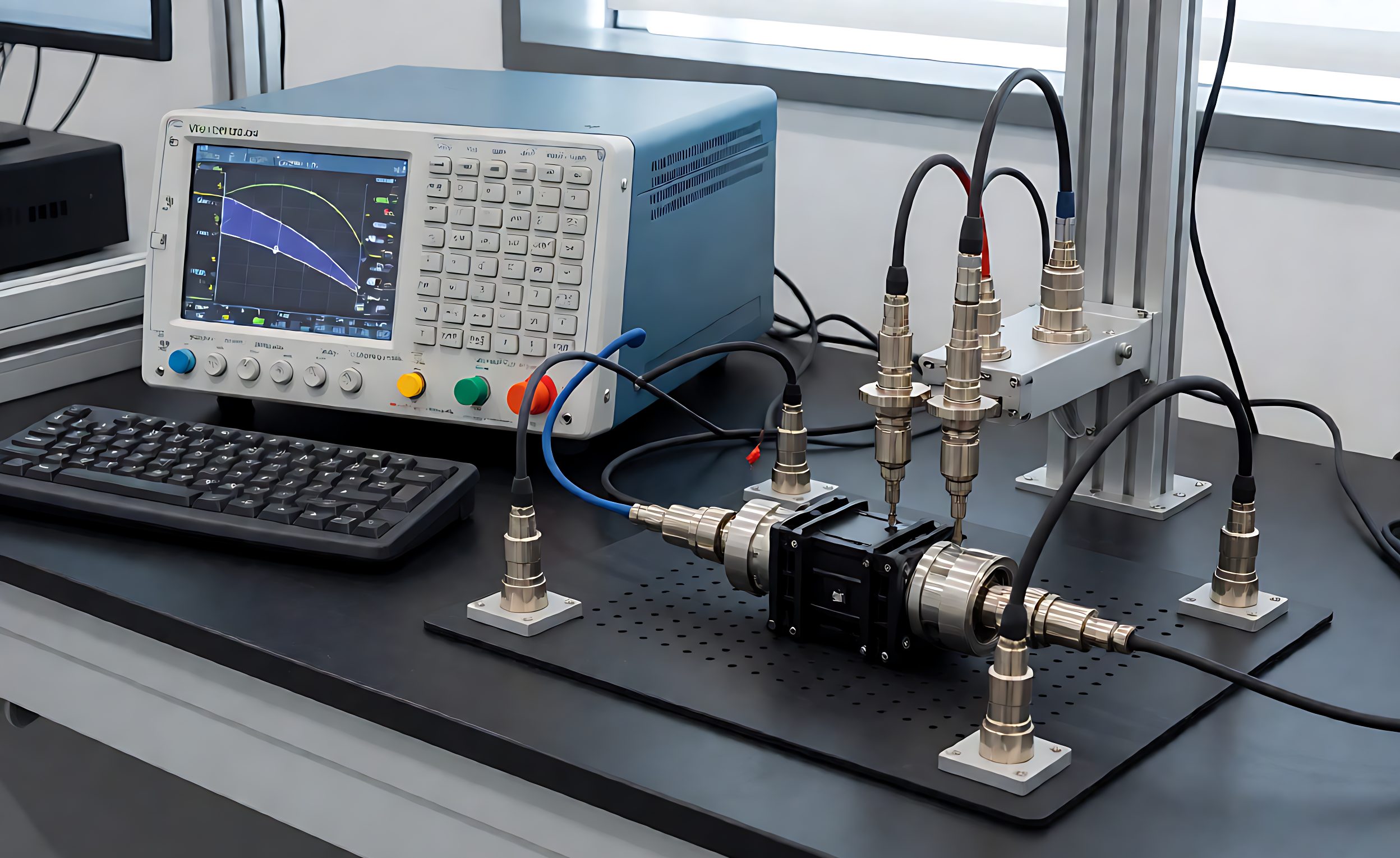
Testing falls into two families. Frequency-domain measurement sweeps the assembly across a range of frequencies and reports how much energy arrives and how much comes back. Time-domain measurement sends a fast edge and looks at what reflections and timing it produces. Both describe the same physical cable from different directions, and a competent test program uses both.
The reported quantities have plain meanings. Insertion loss is how much signal is lost crossing the cable, and it grows with frequency and length because the dielectric and the conductor both absorb energy. Return loss, or its reflection equivalent, is how much signal bounces back from impedance discontinuities, and it is the number that reveals a bad termination. Crosstalk is how much energy leaks from one pair into its neighbor, and skew is the difference in arrival time between pairs, which matters wherever several lanes must arrive together.
Time-domain reflectometry deserves a specific mention because it is the most diagnostic of the common tests. Sending an edge down the line and watching the reflections produces a profile of impedance against distance, which means a defect can be located rather than merely detected. When a batch fails, this is the measurement that says where.

Sampling, First Article and Production Testing
Full parametric testing of every assembly is slow and expensive, and for most programs unnecessary. The usual structure has three tiers. First article is tested thoroughly across the frequency range with a documented report. Production is tested for continuity and insulation resistance on every unit, with parametric testing on a sampling plan. Any design or process change triggers a repeat of the first-article level.
The sampling plan needs to be written down, including how samples are drawn and what happens when one fails. Random drawing across the production run is materially different from testing the first five off the line, because process drift shows up late. A plan that names the sample size, the drawing method and the failure action is enforceable; one that says “sampled per standard practice” is not.
There is one more item that catches programs out: the test fixture. Measurements are made through a fixture, and the fixture has its own contribution that must be calibrated out. A report without a statement of fixture and calibration state is difficult to compare against another laboratory’s report, which is exactly what happens when a buyer second-sources an assembly.
Antecedentes Técnicos
The quantity being controlled is characteristic impedance, the ratio that a transmission line presents to a travelling wave, set by distributed inductance and capacitance per unit length. The discipline that studies how a channel degrades a signal is integridad de la señal, covering loss, reflection, crosstalk and timing together rather than any single number. And the instrument most used to locate where a line departs from its target is a time-domain reflectometer, which converts reflected energy into a picture of impedance against distance.
What to Put in the Test Report Requirement
- State the target and the tolerance. Nominal impedance with a plus and minus figure, not a nominal alone.
- State the frequency range. Loss and reflection figures are meaningless without the band they were measured over.
- Name the quantities. Insertion loss, return loss, crosstalk and skew where they matter, each with a limit.
- Require time domain on first article. It locates defects instead of merely detecting them.
- Require fixture and calibration detail. So results can be compared across laboratories and suppliers.
- Require traceability. Report tied to part number, batch, date and the serials of the units tested.

Six lines, and the specification becomes enforceable. Without them the buyer receives a report that says pass, generated by a method nobody agreed, over a range nobody named, and there is no basis to reject anything.
The broader evidence question is covered in what test reports a cable OEM should provide and in what buyers should require in a test report. Length interacts directly with loss and is treated in SFF-8654 cable length and signal integrity, with buying-side limits in the SlimSAS buying guide. The underlying concepts are introduced in signal integrity as the unseen factor, and qualification of an alternative supplier is set out in second-source qualification.
Preguntas frecuentes
Can impedance be adjusted after the cable is made?
No. Impedance follows geometry and materials, so it is set by conductor size, dielectric and spacing during manufacture.
Why does impedance change at the connector?
The controlled cross-section ends abruptly at the termination, creating a step in impedance that reflects part of the signal.
What is the difference between insertion loss and return loss?
Insertion loss is signal absorbed crossing the cable; return loss is signal reflected back from impedance discontinuities.
Should every assembly be fully tested?
Usually no. Full parametric testing belongs at first article, with continuity on every unit and parametric work on a sampling plan.
Why does the test fixture matter?
The fixture adds its own contribution to the measurement, which must be calibrated out before results are comparable.
What does time-domain testing add?
It produces impedance against distance, so a defect can be located rather than only detected.
How should a sampling plan be written?
With sample size, how samples are drawn across the run, and the action to take when one fails.