Quick answer: A 36-pin cable specification should define the connector at each end, gender, viewing direction, pin mapping, cable length, route and verification method. Buyers should use a controlled drawing and confirm the mating interface with the equipment owner. A production-like sample should be checked for orientation and fit, with electrical results tied to the same assembly revision. The phrase “36-pin cable” alone does not define the wiring or end configuration.
1. Identify the interface at both ends
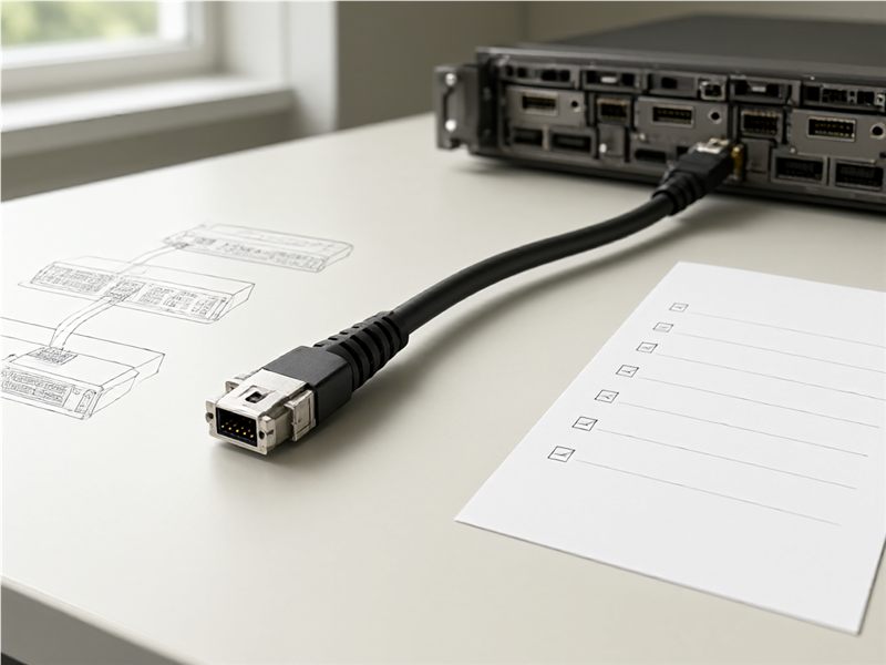
Record the full connector designation, gender and mating equipment for each cable end. Include the connector view used in the drawing, because a front view, wire-side view and installed view can reverse the apparent pin order. Mark end A and end B consistently on the drawing and sample. If the assembly is intended to mate with a named device, list that interface reference and revision. This gives the supplier enough information to identify the intended connector rather than interpreting “CN57 36-pin” as a complete build specification.
2. Make the pin map unambiguous
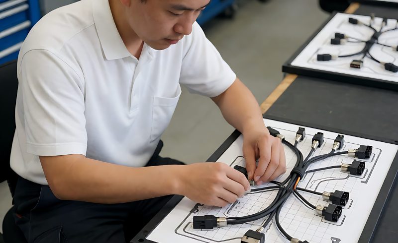
Provide a table that maps each pin at end A to the corresponding pin at end B or to the required termination. State whether the drawing view is from the mating face or wire side and show keying features. Highlight any unused, shielded or special connections according to the equipment owner’s approved design. Have a second reviewer check the mapping against the system documentation before releasing the request. A clear pin map prevents an otherwise correct cable length and connector from being assembled with a reversed or misidentified wiring layout.
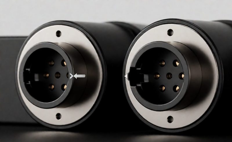
3. Specify cable length and bend direction
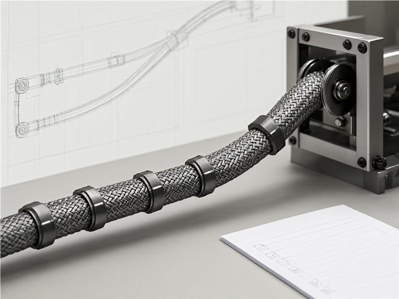
Define the measurement endpoints, allowable length tolerance, cable exit direction and any straight or angled connector requirement. Show where the cable passes through a panel, fixture or enclosure and whether it must bend immediately after the connector. Record the routing envelope and clearance that matter to installation. If the assembly must leave the connector in a particular orientation, illustrate it with a side view and a reference datum. A drawing should communicate how the cable sits in the equipment, not only how it looks when laid flat.
4. Describe construction and operating conditions
Use the application specification to identify conductor, insulation, shielding, jacket and flexibility requirements. Include environmental and movement conditions supplied by the responsible engineering owner. Avoid selecting materials from a generic label or appearance alone. If the cable is static, say so; if it moves with a mechanism, provide the movement path and expected operating pattern. Ask the supplier to list any assumptions or proposed substitutions with the quotation. This keeps construction decisions connected to the real application and makes deviations reviewable.
5. Inspect a representative connector sample
Check the connector body, keying, contact arrangement, latch or retention feature, cable exit and label against the approved drawing. Mate the sample to the actual or equivalent interface and confirm insertion, removal and clearance. Verify that end A and end B markings match the pin-map table. Photograph the installed position from the same directions shown in the drawing. Record any fit issue before approval. A sample fit can reveal access or orientation concerns that are easy to miss in a connector data sheet.
6. Agree on electrical verification
Specify which continuity, mapping, insulation or other checks are required by the system design and who owns those criteria. The supplier should report the assembly identifier, revision, method and result. Keep electrical verification distinct from the mechanical fit review; passing one does not automatically demonstrate the other. If a special test is required, provide the approved test definition rather than asking the supplier to invent a threshold. This creates evidence that can be traced to the exact cable build delivered with the order.
7. Control labels and production packaging
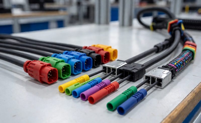
Define labels or packaging information needed for installation, receiving and service. Use end names that match the equipment drawing and avoid abbreviations that could be confused with nearby cable assemblies. Confirm that connector caps or other protective packing are included when the application requires them. Check carton quantity and label data against the purchase order. A well-labeled sample and production pack help installers select the correct assembly and let receiving reconcile the shipment without opening every unit.
8. Retain an approved revision for repeat orders
Store the final connector description, pin map, drawing view, length, construction, sample-fit photos and test evidence under one assembly revision. Identify changes that require review, including contact source, pin mapping, orientation, jacket, length or manufacturing process. When a repeat order arrives, compare its identification and evidence to the approved record. If the equipment interface changes, reopen the cable review rather than assuming an earlier sample remains suitable. Traceable revisions make the assembly easier to source, install and service.
For buyers comparing available product and supplier options, see Longkai CN57 36-pin cable assembly.
Questions buyers often ask
Why does the connector viewing direction matter?
The apparent pin order can change between mating-face and wire-side views, so the drawing must state the view and keying reference.
What is the minimum information for a 36-pin cable quote?
Provide both connector ends, gender, pin map, cable length and route, construction requirements, operating conditions and verification method.
Does continuity testing prove the cable fits the equipment?
No. Electrical checks and mechanical fit should be reviewed as separate acceptance items.
When should a new sample be approved?
Request review when pin map, connector, orientation, construction, length or another controlled requirement changes.